Image stabilization control apparatus, optical apparatus and storage medium storing image stabilizing control program

a control apparatus and image stabilization technology, applied in the field of image stabilization apparatuses, can solve the problems of vector cannot be detected, insufficient image stabilization control, deterioration of detection accuracy, etc., and achieve good image stabilization control

Active Publication Date: 2016-10-27
CANON KK
View PDF7 Cites 25 Cited by
  • Summary
  • Abstract
  • Description
  • Claims
  • Application Information

AI Technical Summary

Benefits of technology

[0006]The present invention provides an image stabilization control apparatus and an optical apparatus provided therewith capable of performing a good image stabilization control using a shake sensor in still image capturing in which a motion vector cannot be obtained.
[0010]The present invention provides as yet another aspect thereof a non-transitory computer-readable storage medium storing an image stabilizing control program as a computer program to cause a computer to perform an image stabilization control process to reduce image blur due to shaking of an optical apparatus by using a shake detection signal obtained through detection of the shaking of the optical apparatus and a motion vector detection signal indicating a motion vector detected in an image signal produced through image capturing using the optical apparatus. The image stabilization control process includes extracting a first shake signal from the shake detection signal, the first shake signal being a frequency component whose frequency is higher than a predetermined frequency, producing, by using the motion vector detection signal, a predicted shake signal indicating a predicted value of the shaking, combining the first shake signal with the predicted shake signal to produce a second shake signal, performing the image stabilization control by using the second shake signal, and extracting a specific motion vector signal from the motion vector detection signal, the specific motion vector signal being a frequency component whose frequency is lower than the predetermined frequency. The program causes the computer to perform the image stabilization control process by using the second shake signal in still image capturing and to produce the predicted shake signal by using the specific motion vector signal.

Problems solved by technology

However, use of the shake sensor has a problem that a low frequency noise (error component), called a drift, overlaps a sensor output corresponding to an actual camera shake, which may deteriorate a detection accuracy for the camera shake and thus result in an insufficient image stabilization control.
However, the motion vector cannot be detected in an image sensor exposure time for still image capturing, which disables an image stabilization control using the motion vector.

Method used


Image

  • Image stabilization control apparatus, optical apparatus and storage medium storing image stabilizing control program
  • Image stabilization control apparatus, optical apparatus and storage medium storing image stabilizing control program
  • Image stabilization control apparatus, optical apparatus and storage medium storing image stabilizing control program

Examples


embodiment 1

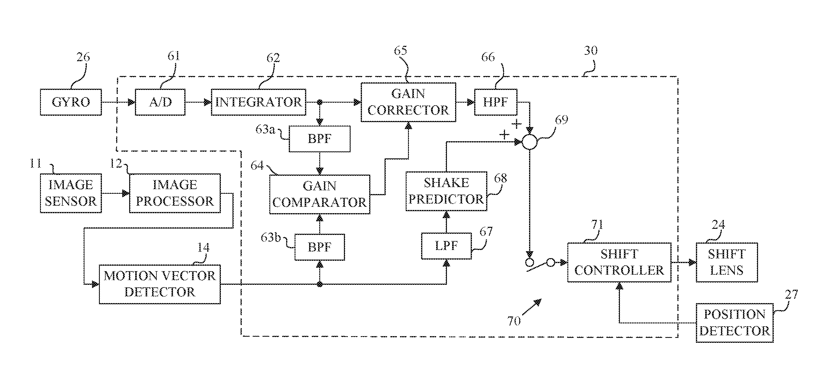
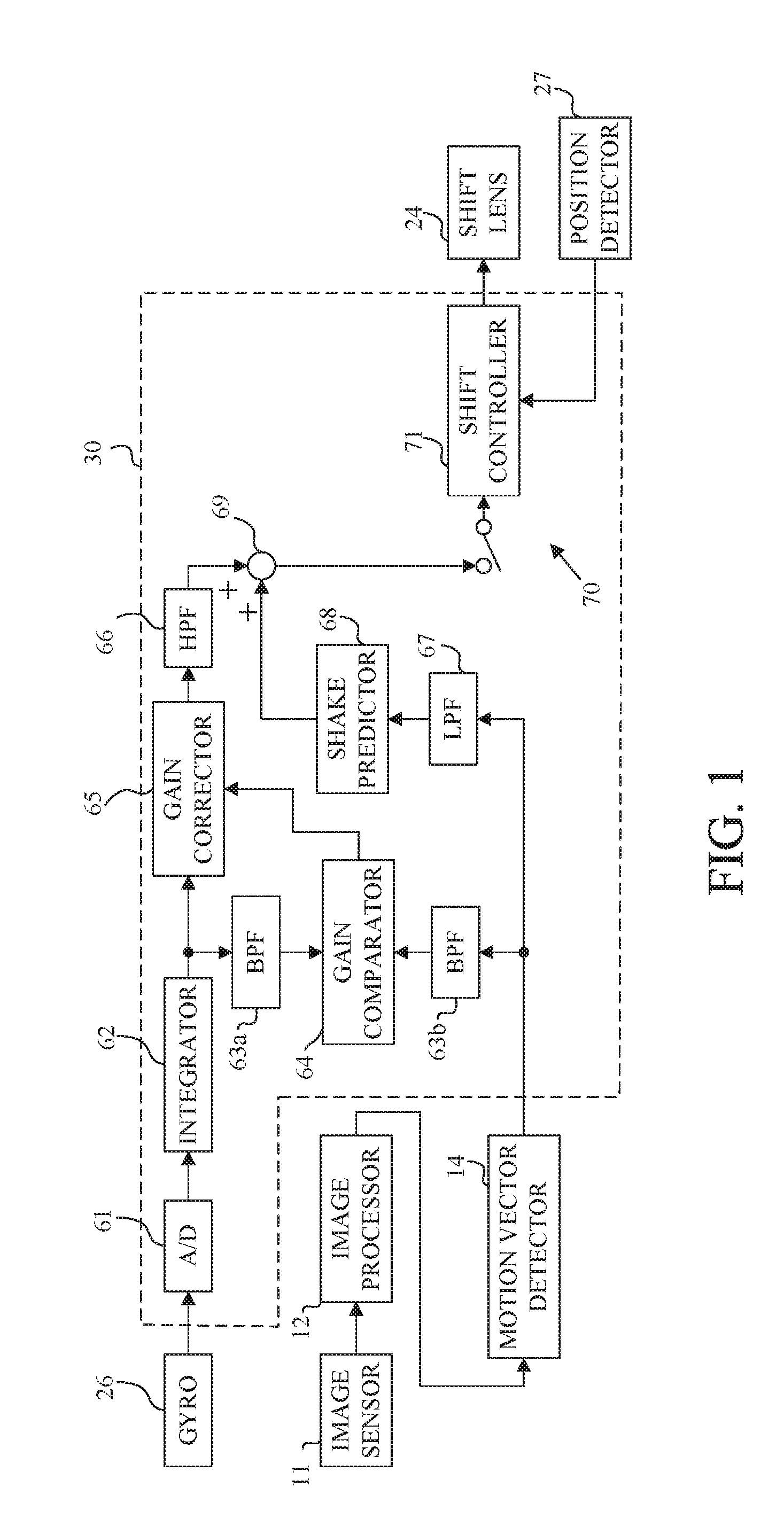
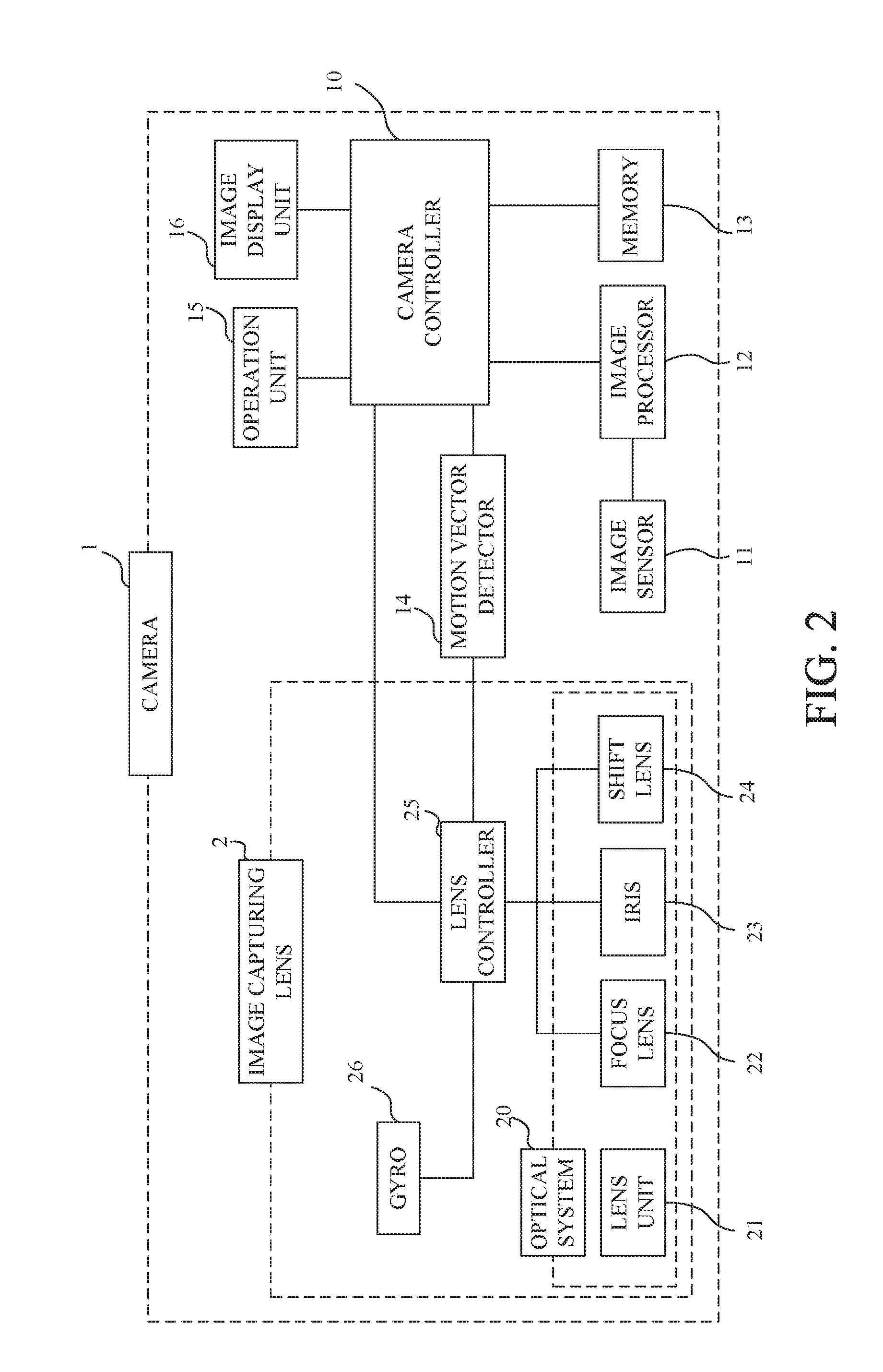
[0026]FIG. 2 illustrates a configuration of a digital camera 1 as an image capturing apparatus (optical apparatus) provided with an image stabilization control apparatus that is a first embodiment (Embodiment 1) of the present invention. The camera 1 as a lens-integrated camera includes an image capturing lens 2, an image sensor 11 that photoelectrically converts (that is, captures) an optical image formed by an image capturing optical system 20 provided in the image capturing lens 2, and an image processor 12 that produces, using an image capturing signal output from the image sensor 11, a video (moving image) signal and a still image signal.

[0027]The camera 1 further includes a memory 13 described later, a motion vector detector (motion vector detecting unit) 14 that detects a motion vector from the video signal, an operation unit 15 that detects user's operations, an image displaying unit 16 that displays the image signals, and a camera controller (camera control unit) 10 that go...

embodiment 2

[0139]With referring to FIG. 8, description will be made of a digital camera provided with an image stabilization controller 30′ as an image stabilization apparatus that is a second embodiment (Embodiment 2) of the present invention.

[0140]Although Embodiment 1 described the case of starting the image stabilization control in response to the input of the second release signal SW2 that instructs the start of the still image exposure, this embodiment performs the image stabilization control before the still image exposure so as to display a live view image with little image blur on the image display unit 16. Specifically, the image stabilization controller 30′ starts the image stabilization control in response to an input of the first release signal SW1 from the operation unit 15 that instructs a start of the image capturing preparation operation.

[0141]Until the input of the second release signal SW2 from the operation unit 15, the image stabilization controller 30′ performs an image s...

embodiment 3

[0154]With referring to FIG. 9, description will be made of a digital camera provided with an image stabilization controller 30″ as an image stabilization apparatus that is a third embodiment (Embodiment 3) of the present invention.

[0155]This embodiment performs, as in Embodiment 2, the image stabilization control also in the image capturing preparation period and however performs it using, not the motion vector detection signal, but the gyro shake detection signal. A configuration of the camera in this embodiment is identical to that of the camera 1 in Embodiment 1, and therefore description thereof is omitted. In FIG. 9, components in the image stabilization controller 30″ common to those in the image stabilization controllers 30 and 30′ in Embodiments 1 and 2 (FIGS. 1 and 8) are denoted by the same reference numerals as those in Embodiments 1 and 2, and description thereof is omitted.

[0156]In FIG. 9, reference numeral 76 denotes a subtractor that outputs a difference between the ...


PUM


Abstract

The image stabilization control apparatus includes a shake extracting unit extracting a first shake signal whose frequency is higher than a predetermined frequency from a shake detection signal, a predicting unit producing, by using a motion vector detection signal, a predicted shake signal indicating a predicted value of shaking of an optical apparatus, a combining unit combining the first shake signal with the predicted shake signal to produce a second shake signal, a controlling unit performing an image stabilization control using the second shake signal, and a motion vector extracting unit extracting a specific motion vector signal whose frequency is lower than the predetermined frequency from the motion vector detection signal. The controlling unit performs the image stabilization control using the second shake signal in still image capturing, and the predicting unit produces the predicted shake signal by using the specific motion vector signal.

Description

BACKGROUND OF THE INVENTION[0001]1. Field of the Invention[0002]The present invention relates to an image stabilization apparatus capable of reducing image blur in optical apparatus such as digital cameras and interchangeable lenses.[0003]2. Description of the Related Art[0004]An optical image stabilization, which is an image stabilization technique to correct (reduce), in still image capturing with a digital camera, image blur due to shaking of the camera caused by user's hand jiggling, is proposed that moves (shifts) a lens or an image sensor (such as a CMOS sensor) with respect to an image capturing optical apparatus. The shaking of the camera (camera shake) is detected by using a shake sensor such as an angular velocity sensor (gyro sensor) or by calculating a motion vector between frame images constituting a captured motion image as disclosed in Japanese Patent Laid-Open No. 05-122590.[0005]However, use of the shake sensor has a problem that a low frequency noise (error compone...

Claims


Application Information

Patent Timeline
Patent Type & Authority Applications(United States)
IPC IPC(8): H04N5/232
CPCH04N5/23287H04N23/6811H04N23/6812H04N23/687
Inventor KAJIMURA, FUMIHIRO
Owner CANON KK
Why Eureka
Try Eureka