Cleaning apparatus and liquid ejection apparatus and liquid ejection surface cleaning method

a technology of liquid ejection and cleaning method, which is applied in the direction of printing, etc., can solve the problems of abnormal ejection volume, and inability to properly eject ink, and achieve the effect of preventing the damage of the lyophobic film (lyophobic treatment) on the liquid ejection surfa

Inactive Publication Date: 2008-10-02
FUJIFILM CORP
View PDF5 Cites 22 Cited by
  • Summary
  • Abstract
  • Description
  • Claims
  • Application Information

AI Technical Summary

Benefits of technology

[0045]According to the present invention, since a liquid ejection surface is wetted by fine liquid particles sprayed from a nozzle, then wiping of the liquid ejection surface by a wiping device is a wet wip...

Problems solved by technology

In such an inkjet recording apparatus, ink is liable to adhere to the ink ejection surface (nozzle surface) of the inkjet head, and if residual ink of this kind solidifies, then it can cause ejection abnormalities, such as abnormalities in the ink ejection volume or abnormalities in the ejection direction.
In the invention described in Japanese Patent Application Publication No. 2006-289809, the meniscus inside the nozzles breaks down when the cleaning liquid is blown onto the nozzle surface, and therefore, unless the meniscus is restored for the next ink ejection operation, it is not possible to eject ink properly.
Moreover, a large amount of cleaning liquid enters into th...

Method used


Image

  • Cleaning apparatus and liquid ejection apparatus and liquid ejection surface cleaning method
  • Cleaning apparatus and liquid ejection apparatus and liquid ejection surface cleaning method
  • Cleaning apparatus and liquid ejection apparatus and liquid ejection surface cleaning method

Examples


first embodiment

Composition of Cleaning Apparatus

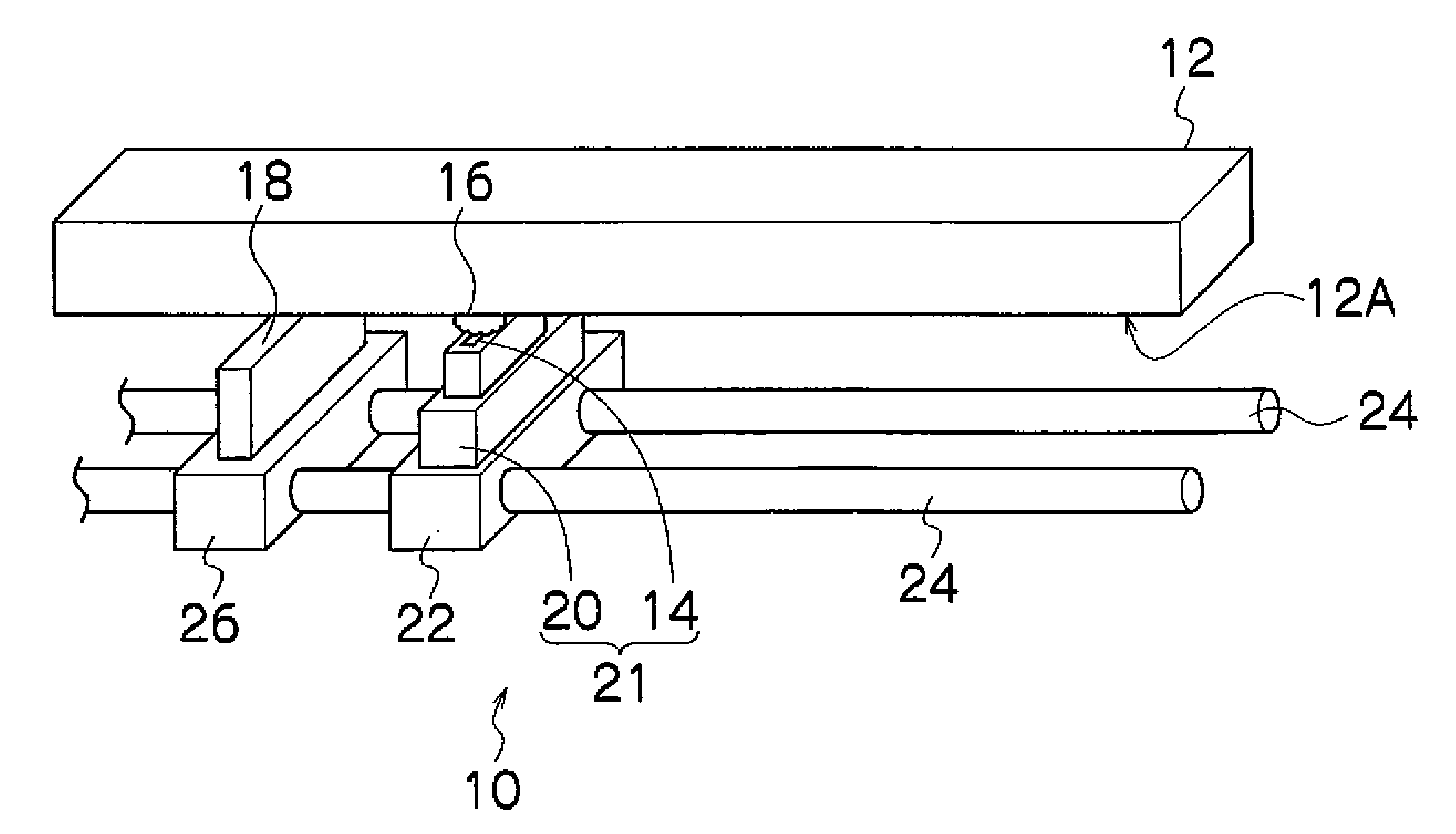
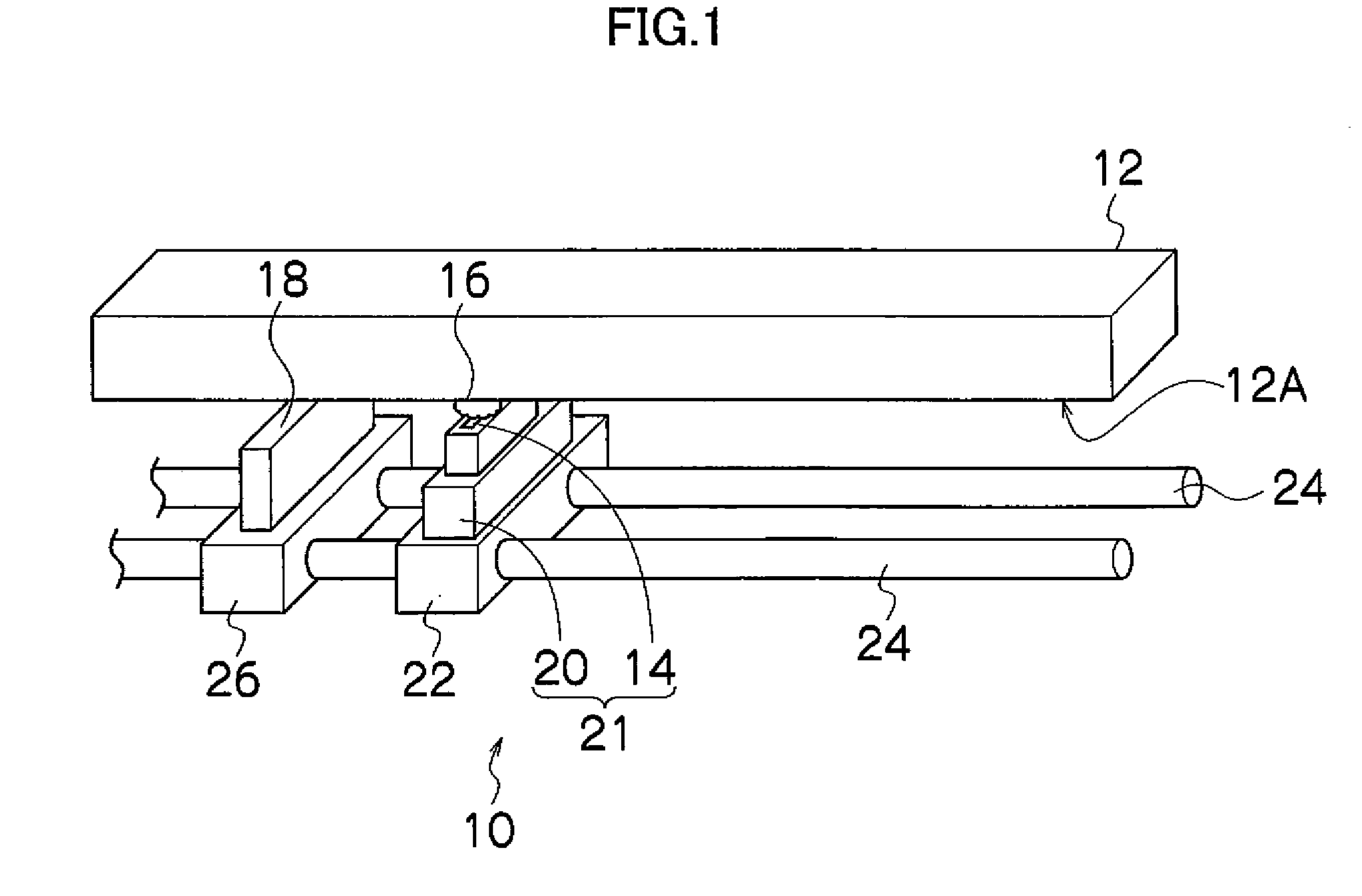
[0063]FIG. 1 is an oblique view showing the general composition of a cleaning apparatus 10 relating to an embodiment of the present invention. As shown in FIG. 1, the cleaning apparatus 10 is provided on the liquid ejection surface (nozzle surface) 12A side of a liquid ejection head (inkjet head) 12 (directly below the liquid ejection head), which is provided in a liquid ejection apparatus, such as an inkjet recording apparatus. The cleaning apparatus 10 sprays liquid in the form of fine liquid particles (fine liquid droplets) 16 having a diameter of approximately several μm from a fine liquid particle ejection port 14 (a nozzle), and after the fine liquid particles 16 have been deposited on and caused to aggregated on the liquid ejection surface (hereinafter, called the “ejection surface”) 12A of the liquid ejection head (hereinafter, called the “head”) 12, the ejection surface 12A which has been wetted by the fine liquid particles 16 is wiped with ...

second embodiment

Composition of Cleaning Apparatus

[0117]Next, a cleaning apparatus according to a second embodiment of the present invention will be describe. FIG. 6 shows a front view diagram of a cleaning apparatus 100. In FIG. 6, parts which are the same as or similar to FIG. 2 are labeled with the same reference numerals and further explanation thereof is omitted here.

[0118]The cleaning apparatus 100 shown in FIG. 6 differs from the cleaning apparatus 10 shown in FIG. 2 in that it comprises an adhering material determination sensor 102 which determines adhering material on the ejection surface 12A of the head 12. In other words, in the cleaning apparatus 100 shown in FIG. 6, the adhering material determination sensor 102 is installed on a carriage 101, which is independent of the carriage 22 on which the fine liquid particle outlet port 14 and the liquid storage chamber 20 are mounted.

[0119]More specifically, the carriage 101 which is movable in the lengthwise direction of the head 12 in a plane...

application example

[0158]Next, a liquid ejection apparatus which is equipped with a cleaning apparatus relating to an embodiment of the present invention will be described as an application example of the first embodiment and the second embodiment described above. The liquid ejection apparatus shown in FIG. 9 is an inkjet recording apparatus 200 which can form desired color images by means of color inks ejected onto a recording medium. Firstly, the overall composition of the inkjet recording apparatus shown in FIG. 9 will be described.

[0159]As shown in FIG. 9, the inkjet recording apparatus 200 comprises: a printing unit 212 having a plurality of inkjet heads (hereinafter, called “heads”) 212K, 212C, 212M, and 212Y provided for ink colors of black (K), cyan (C), magenta (M), and yellow (Y), respectively; an ink storing and loading unit 214 for storing inks of K, C, M and Y to be supplied to the heads 212K, 212C, 212M, and 212Y; a paper supply unit 218 for supplying recording paper 216 which is a recor...


PUM


Abstract

A cleaning apparatus which cleans a liquid ejection surface of a liquid ejection head, has: a liquid storage chamber which stores a first liquid; a vibrating device which converts the first liquid stored in the liquid storage chamber into fine particles of the first liquid; a fine liquid particle outlet port from which the fine particles of the first liquid is sprayed toward the liquid ejection surface; and a wiping device which wipes the liquid ejection surface after the fine particles of the first liquid sprayed from the fine liquid particle outlet port are deposited on the liquid ejection surface.

Description

BACKGROUND OF THE INVENTION[0001]1. Field of the Invention[0002]The present invention relates to a cleaning apparatus, a liquid ejection apparatus and a liquid ejection surface cleaning method, and more particularly, to technology for maintaining the liquid ejection surface of a liquid ejection head.[0003]2. Description of the Related Art[0004]In general, an inkjet recording apparatus which forms a desired image by ejecting ink droplets from an inkjet head onto a recording medium is widely used as a generic image forming apparatus. In such an inkjet recording apparatus, ink is liable to adhere to the ink ejection surface (nozzle surface) of the inkjet head, and if residual ink of this kind solidifies, then it can cause ejection abnormalities, such as abnormalities in the ink ejection volume or abnormalities in the ejection direction. Consequently, it is necessary to carry out periodic maintenance (cleaning) of the ink ejection surface of the inkjet head.[0005]One method for cleaning...

Claims


Application Information

Patent Timeline
IPC IPC(8): B41J2/165
CPCB41J2/16552B41J2/16585
Inventor INOUE, HIROSHI
Owner FUJIFILM CORP
Why Eureka
Try Eureka