Liquid discharge head and liquid discharge apparatus

Inactive Publication Date: 2008-10-02
CANON KK
View PDF4 Cites 16 Cited by
  • Summary
  • Abstract
  • Description
  • Claims
  • Application Information

AI Technical Summary

Benefits of technology

[0019]One objective of the present invention is to provide a liquid discharge head comprising a piezoelectric element, the polarization characteristic of which can be recovered without having to apply an electrical field in the opposite direction when applying an electrical field during driving, and a liquid discharge apparatus.
[0021]According to the present invention, a liquid discharge head that includes a piezoelectric element, the polarization characteristic of which can be recovered without having to apply an electrical field in the opposite direction when an electrical field is applied during driving, and a liquid discharge apparatus.

Problems solved by technology

It is generally known that when a piezoelectric device has been driven for a long time, a frequently noted phenomenon is deterioration of the displacement function.
However, according to the method whereby the polarization characteristic is recovered by applying an electrical field equal to or higher than a coercive electrical field in the direction opposite to that at the driving time, a problem that the cost will be increased because a circuit provided for driving will become complicated.
Further, since an electrical field equal to or higher than a coercive electrical field is applied in the direction opposite to that at the driving time, there is another problem in that a load imposed on a piezoelectric device will be increased.
However, even in a case wherein an electrical field applied to the anti-ferroelectric material is zero, it is assumed that not too great an effect should be expected for the recovery of the polarization characteristic.
However, it is very difficult to actually provide a ferroelectric material having a hysteresis characteristic, as shown in FIG. 12.
Therefore, it can be ascertained that it is very difficult for the hysteresis characteristic shown in FIG. 12 to be provided using a ferroelectric material.

Method used


Image

  • Liquid discharge head and liquid discharge apparatus
  • Liquid discharge head and liquid discharge apparatus
  • Liquid discharge head and liquid discharge apparatus

Examples


first embodiment

[0036]A first embodiment of the present invention will be described while referring to FIGS. 1 to 8.

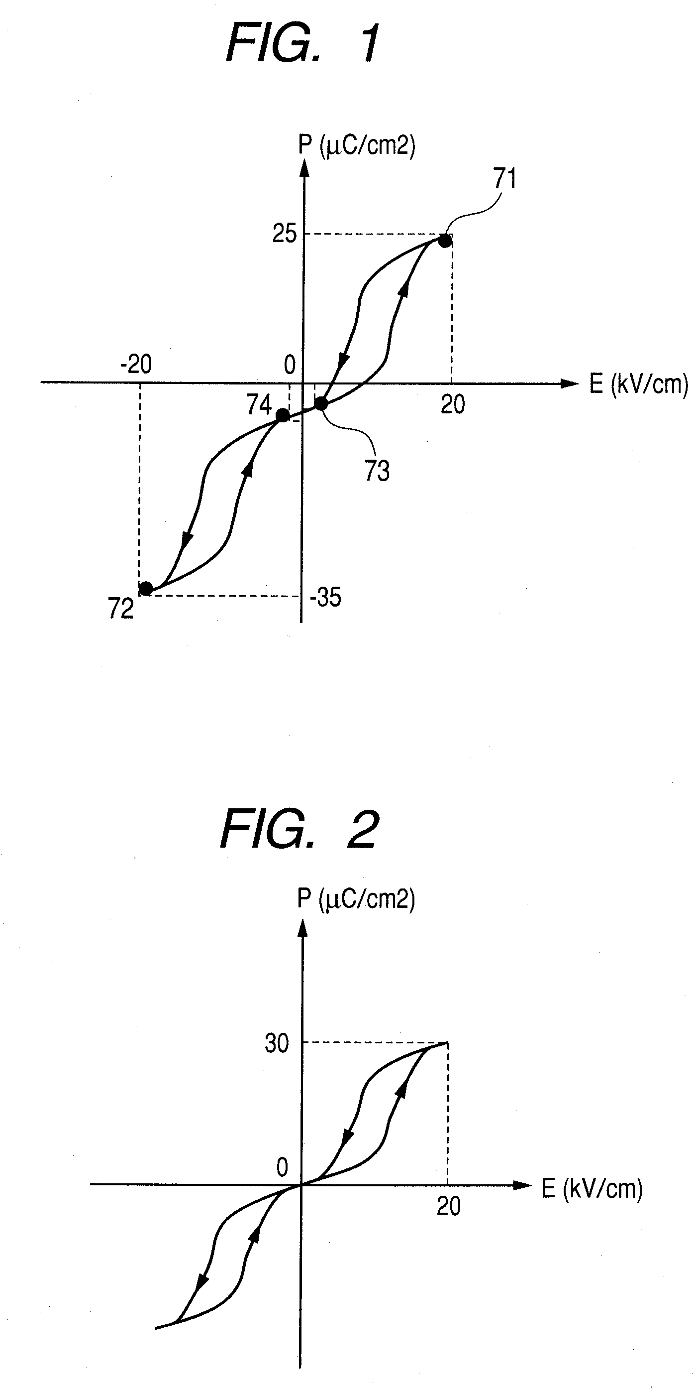
[0037]FIG. 1 is a diagram illustrating a polarization-field hysteresis characteristic of a piezoelectric element according to this embodiment. The piezoelectric element of this embodiment is formed of a piezoelectric material including an anti-ferroelectric member. A method for obtaining the hysteresis characteristic shown in FIG. 1 will now be described.

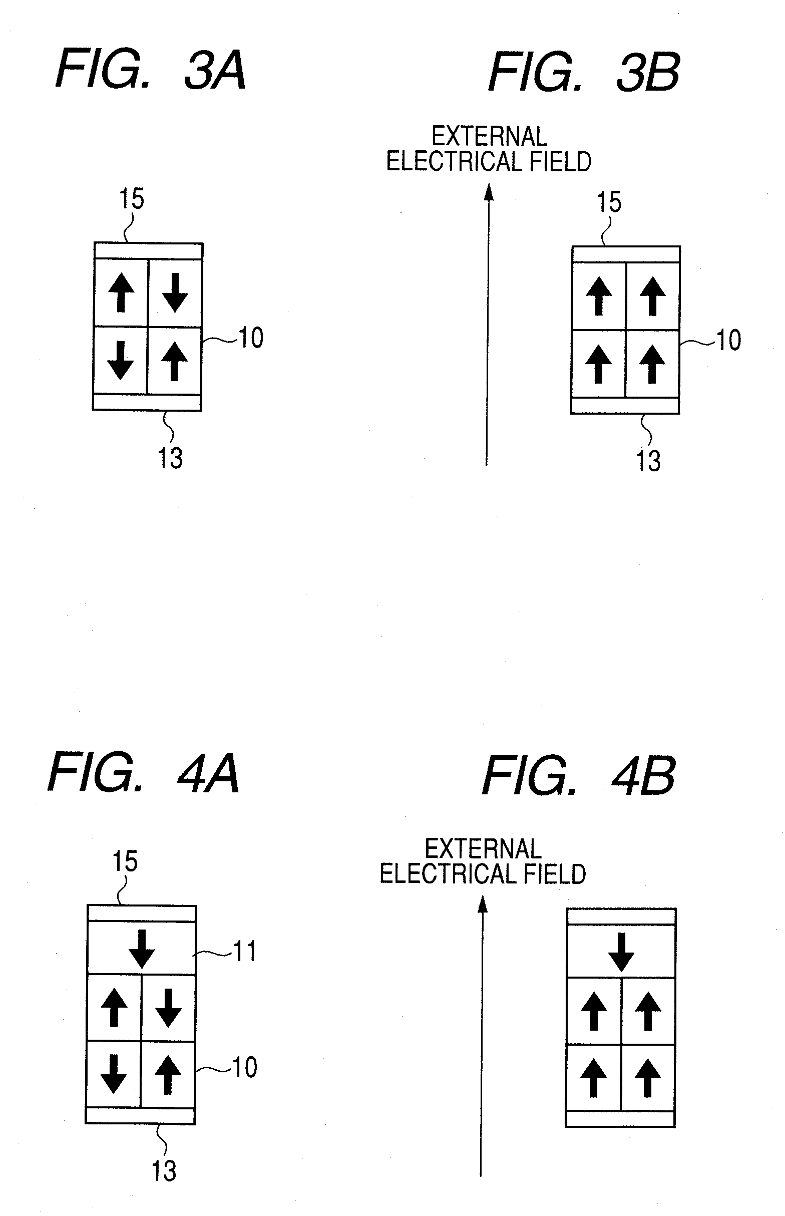
[0038]FIG. 2 is a diagram illustrating a polarization-field hysteresis characteristic for an anti-ferroelectric member, and FIGS. 3A and 3B are schematic cross-sectional views of the polarization of the anti-ferroelectric member that exhibits the hysteresis characteristic shown in FIG. 2. As shown in FIG. 3A, when an external electrical field is not present, polarization of the anti-ferroelectric member indicates an opposite direction for each unit lattice (unit cell) of a crystal, and a polarization value for the entire anti-ferroele...

second embodiment

[0062]A second embodiment of the present invention will now be described while referring to FIG. 9. A polarization-field hysteresis characteristic for an anti-ferroelectric member according to this embodiment is shown in FIG. 9.

[0063]The structure and the manufacturing method for an anti-ferroelectric member and a liquid discharge head for this embodiment are substantially the same as those for the first embodiment. Therefore, the same reference numerals as are used for the first embodiment are provided for the individual components that are described for this embodiment.

[0064]The structure and the manufacturing method of the anti-ferroelectric member according to this embodiment will be described while referring to FIG. 3. An anti-ferroelectric member 10 in this embodiment internally has a space-charge polarization. In this embodiment, PZS, for which aging has been performed, for example, is employed as the material used for the anti-ferroelectric member 10. A PZS solution is appli...

third embodiment

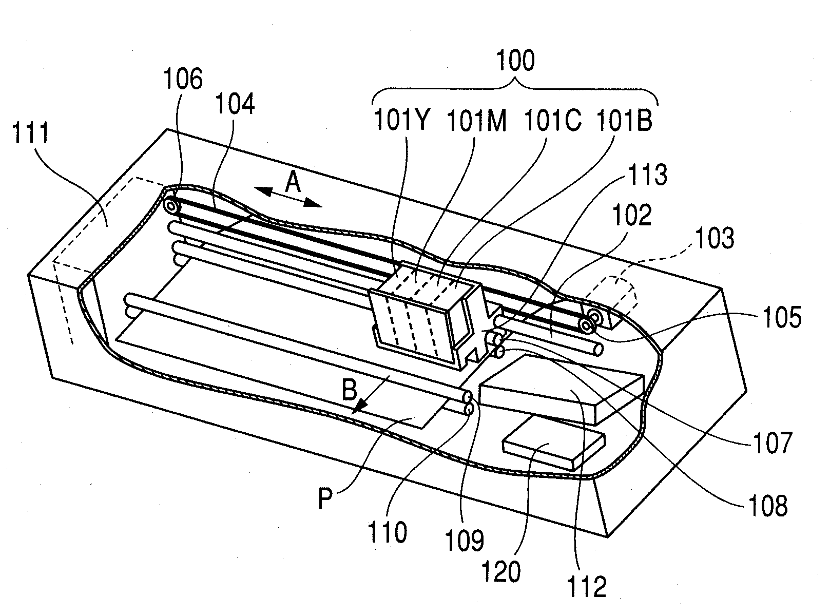
[0067]A liquid discharge apparatus according to a third embodiment of the present invention will now be described while referring to FIG. 10. FIG. 10 is a perspective view illustrating a liquid discharge apparatus for which the present invention can be applied.

[0068]The liquid discharge apparatus of this embodiment includes feeding rollers 109 and 110 for conveying a recording medium P. A recording medium P. when inserted into the liquid discharge apparatus, is conveyed by the feeding rollers 109 and 110 to a recording enabled area for a liquid discharge head unit 100.

[0069]The liquid discharge head unit 100 is guided, by two guide shafts 107 and 102, so as to be movable in a direction in which the guide shafts are extended (main scanning direction), and reciprocally scans the recording area. In this embodiment, the direction in which the liquid discharge head 100 scans is regarded as the main scanning direction, and the direction in which the recording medium P is conveyed is regar...


PUM


Abstract

A liquid discharge head is provided, which includes a piezoelectric element for which the polarization characteristic can be recovered without having to apply an electrical field in a direction opposite to that in which an electrical field is to be applied during driving. A piezoelectric element provided for a liquid discharge head of the present invention includes a field-polarization hysteresis characteristic that has, at the least, one hysteresis loop. A saturation polarization point and a critical polarization point, on one hysteresis loop for the hysteresis characteristic, are positioned in the same field polarity, and different signs are provided for a polarization value at the saturation polarization point and for the polarization value at the critical polarization point.

Description

BACKGROUND OF THE INVENTION[0001]1. Field of the Invention[0002]The present invention relates to a liquid discharge head that includes a piezoelectric device, and a liquid discharge apparatus on which the liquid discharge head is mounted.[0003]2. Description of the Related Art[0004]A liquid discharge head is employed for an image recording apparatus, such as a printer. The liquid discharge head includes: discharge ports, used to discharge a liquid; individual liquid chambers, connected to the discharge ports through orifice communication portions; and discharge means, for discharging liquid held in the individual liquid chambers. The liquid discharge head expands or shrinks the individual liquid chambers to discharge liquid therein through the discharge ports, through the orifice communication portions.[0005]As this type of liquid discharge head, there is a piezo-type liquid discharge head wherein, to discharge a liquid, a voltage is applied to a piezoelectric device, equipped with ...

Claims


Application Information

Patent Timeline
IPC IPC(8): B41J2/045B41J2/055B41J2/135B41J2/14B41J2/16H01L41/09H01L41/187H01L41/22H01L41/253
CPCB41J2/14233
Inventor MIURA, KAORU
Owner CANON KK
Why Eureka
Try Eureka