Magnetic head for perpendicular magnetic recording and method of manufacturing same, the magnetic head including pole layer and two shields that sandwich the pole layer

a perpendicular magnetic and recording technology, applied in the direction of heads with metal sheet cores, instruments, photomechanical equipment, etc., can solve problems such as track width variations, and achieve the effect of reducing the effect of standing waves and defining track width with precision

Active Publication Date: 2008-10-02
TDK CORPARATION +1
View PDF15 Cites 5 Cited by
  • Summary
  • Abstract
  • Description
  • Claims
  • Application Information

AI Technical Summary

Benefits of technology

[0029]According to the invention, since the antireflection film is disposed between the first shield and the first gap layer or between the first gap layer and the pole layer, it is possible to reduce the effects of a standing wave when the pole layer is formed, and it is thereby possible to implement the pole layer free from defects and capable of defining the track width with precision.

Problems solved by technology

Furthermore, if the wall surface of the frame forming the groove has irregularities, great variations occur in width of the pole layer, which results in variations in track width.

Method used


Image

  • Magnetic head for perpendicular magnetic recording and method of manufacturing same, the magnetic head including pole layer and two shields that sandwich the pole layer
  • Magnetic head for perpendicular magnetic recording and method of manufacturing same, the magnetic head including pole layer and two shields that sandwich the pole layer
  • Magnetic head for perpendicular magnetic recording and method of manufacturing same, the magnetic head including pole layer and two shields that sandwich the pole layer

Examples


first embodiment

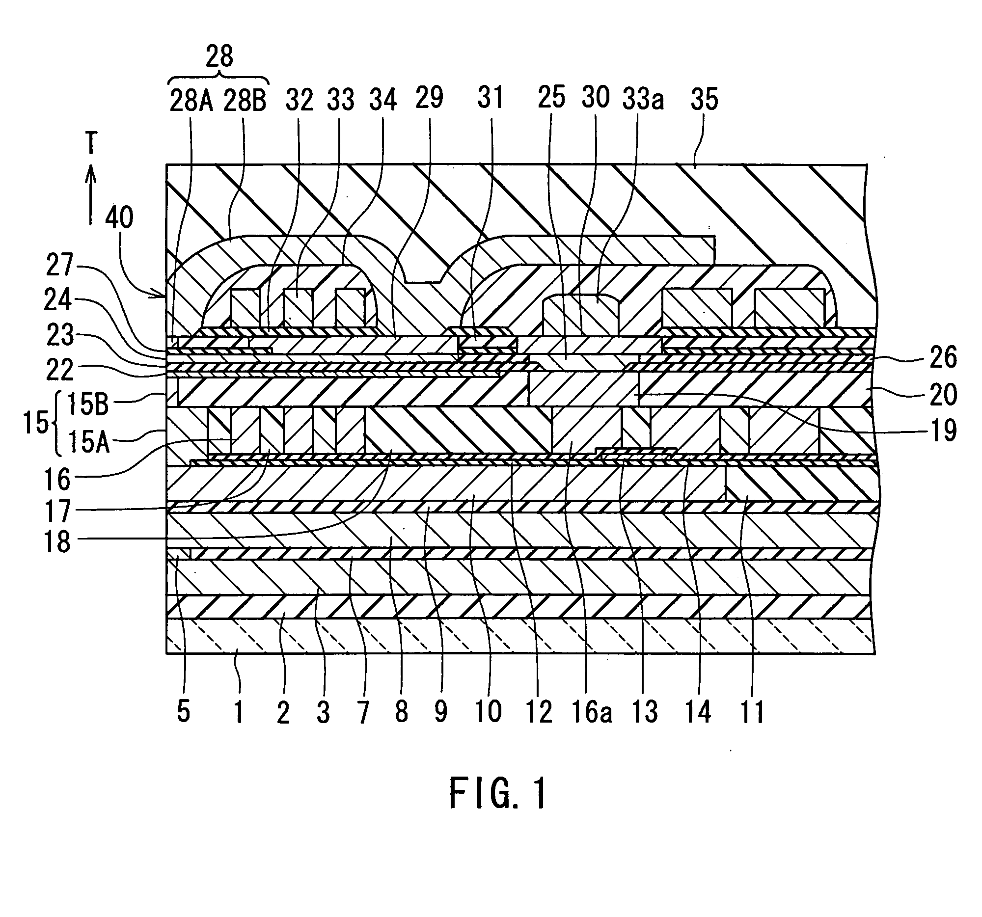
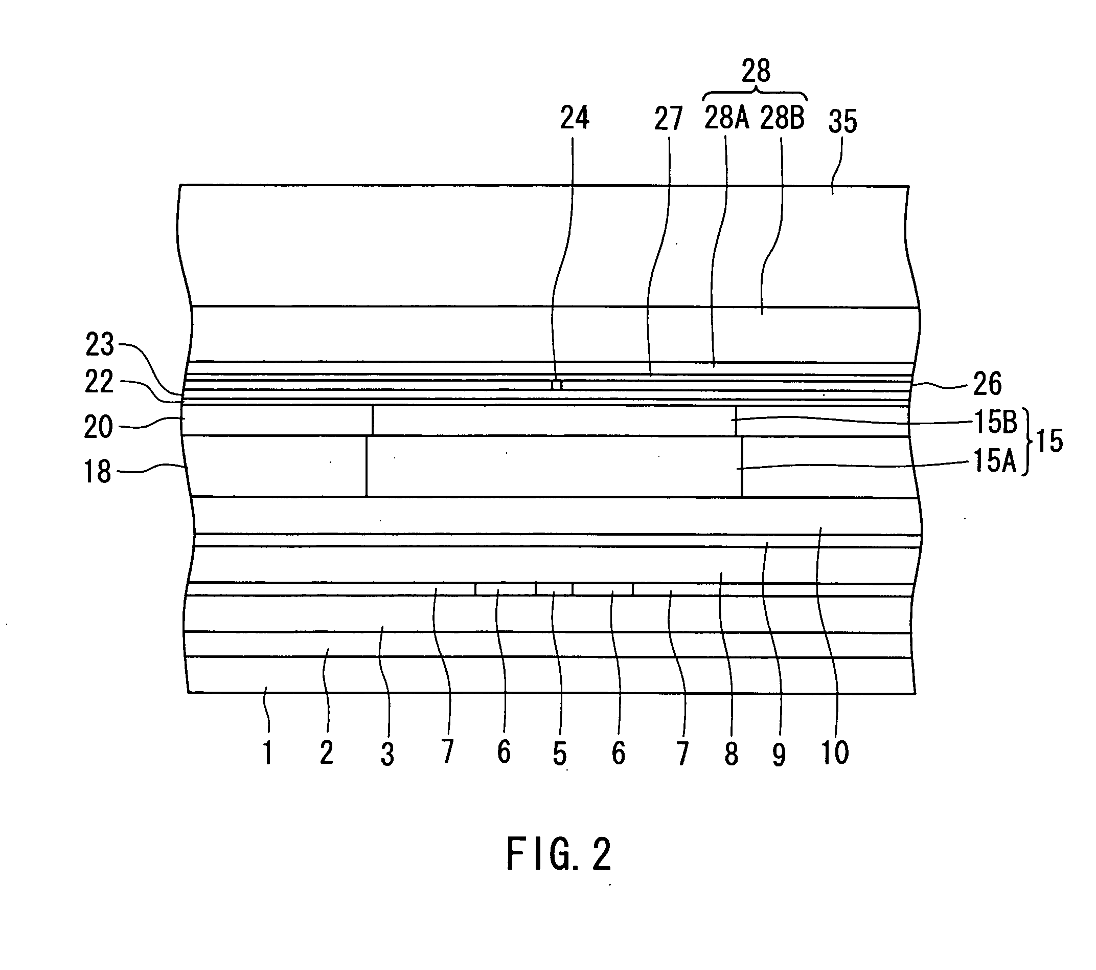
[0067]Preferred embodiments of the invention will now be described in detail with reference to the accompanying drawings. Reference is now made to FIG. 1 and FIG. 2 to describe the configuration of a magnetic head for perpendicular magnetic recording (hereinafter simply called a magnetic head) of a first embodiment of the invention. Here is given an example of a magnetic head in which a TMR element utilizing a tunneling magnetoresistive effect is employed as the MR element. FIG. 1 is a cross-sectional view for illustrating the configuration of the magnetic head. FIG. 2 is a front view of the medium facing surface of the magnetic head. FIG. 1 illustrates a cross section orthogonal to the medium facing surface and the top surface of a substrate. The arrow indicated with T in FIG. 1 shows the direction of travel of a recording medium.

[0068]As shown in FIG. 1, the magnetic head of the embodiment has a medium facing surface 40 that faces toward a recording medium. As shown in FIG. 1 and ...

second embodiment

[0145]Reference is now made to FIG. 35 and FIG. 36 to describe a second embodiment of the invention. FIG. 35 is a cross-sectional view for illustrating the configuration of a magnetic head of the second embodiment. FIG. 36 is a front view of the medium facing surface of the magnetic head of the second embodiment. FIG. 35 illustrates a cross section orthogonal to the medium facing surface and the top surface of the substrate. The arrow indicated with T in FIG. 35 shows the direction of travel of the recording medium.

[0146]In the magnetic head of the second embodiment, the antireflection film 22 is disposed on the first gap layer 23, that is, between the first gap layer 23 and the pole layer 24, not on the second layer 15B and the insulating layer 20.

[0147]In a method of manufacturing the magnetic head of the second embodiment, after the insulating layer 20 is formed in the step shown in FIG. 13, the first gap layer 23 is formed instead of forming the antireflection film 22. Next, thr...


PUM

PropertyMeasurementUnit
distanceaaaaaaaaaa
distanceaaaaaaaaaa
heightaaaaaaaaaa

Abstract

A magnetic head incorporates: a medium facing surface; a coil; a pole layer; first and second shields disposed to sandwich the pole layer therebetween; a first gap layer disposed between the first shield and the pole layer; a second gap layer disposed between the second shield and the pole layer; and a substrate. The first shield is located closer to the substrate than the second shield. The magnetic head further incorporates an antireflection film disposed between the first shield and the first gap layer or between the first gap layer and the pole layer. The pole layer is formed by frame plating.

Description

BACKGROUND OF THE INVENTION[0001]1. Field of the Invention[0002]The present invention relates to a magnetic head for perpendicular magnetic recording that is used for writing data on a recording medium by means of a perpendicular magnetic recording system and a method of manufacturing such a magnetic head, and to a head assembly and a hard disk drive each of which includes the magnetic head for perpendicular magnetic recording.[0003]2. Description of the Related Art[0004]For magnetic read / write devices such as magnetic disk drives, higher recording density has been constantly required to achieve a higher storage capacity and smaller dimensions. Typically, magnetic heads used in magnetic read / write devices are those having a structure in which a reproducing (read) head having a magnetoresistive element (that may be hereinafter called an MR element) for reading and a recording (write) head having an induction-type electromagnetic transducer for writing are stacked on a substrate.[0005...

Claims


Application Information

Patent Timeline
Patent Type & Authority Applications(United States)
IPC IPC(8): G11B5/147G03C5/00G11B5/54
CPCG11B5/3133Y10T29/49044G11B5/6064G11B5/3163
Inventor HARADA, TATSUYAOTANI, KOICHIKAWANO, HIDETAKAYOKOYAMA, KENJIMATONO, NAOTO
Owner TDK CORPARATION
Why Eureka
Try Eureka