Imaging apparatus

a technology of imaging apparatus and focusing aids, which is applied in the field of imaging apparatus, can solve the problems of increasing the occupied volume, and achieve the effects of reducing the deterioration of optical performance, reducing the occupied volume, and improving the focusing

Inactive Publication Date: 2008-10-02
SONY CORP
View PDF6 Cites 0 Cited by
  • Summary
  • Abstract
  • Description
  • Claims
  • Application Information

AI Technical Summary

Benefits of technology

[0025]Thus, according to an embodiment of the invention, because the whole of an imaging apparatus including a movable part can be made compact, and further because even when a transparent cover member is provided, the cover member need not be made larger, the imaging apparatus for capturing dynamic and/or static images in wide areas can be made compact.
[0026]Further, an embodiment of the invention, when the cover member is provided, because the cover member need not be made larger, even when the material of the cover member is glass for suppressing deterioration in the optical performance su

Problems solved by technology

If such a camera in which the distance from a front lens to an NP point is relatively long is to be rotated arou

Method used


Image

  • Imaging apparatus
  • Imaging apparatus
  • Imaging apparatus

Examples


Embodiment Construction

[0038]Examples of embodiments of the invention will be described below with reference to drawings.

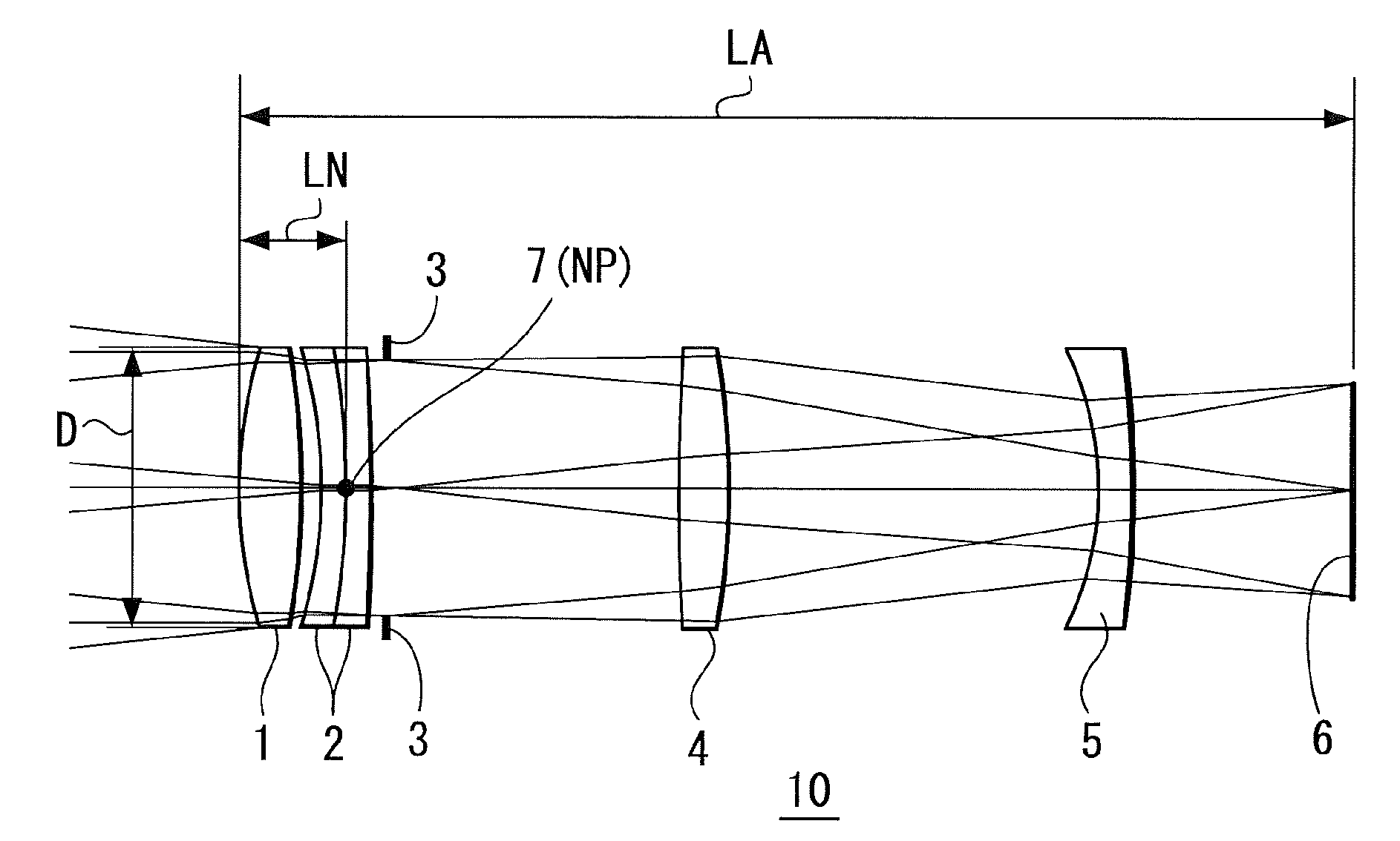
[0039]FIG. 1 is a cross section illustrating the principal part of an example of an imaging apparatus according to an embodiment of the invention. An imaging apparatus (camera) 10 includes a front lens (a lens at the closest side to the imaging subject) 1, a two-piece set lens (combined lens) 2, an aperture diaphragm 3, a lens 4 that is convex on both sides thereof, a lens 5 that is concave on the imaging subject side, and an imaging device 6, which are arranged in this order from the imaging subject side. In this example, the front lens 1, the two-piece set lens 2, the aperture diaphragm 3, the lens 4, and the lens 5 constitute an optical system of the imaging apparatus 10.

[0040]The front lens 1, the two-piece set lens 2, the aperture diaphragm 3, the lens 4, and the lens 5, constituting the optical system, and the imaging device 6 are housed in a camera body (camera barrel, etc.) not ...


PUM


Abstract

An imaging apparatus includes an imaging device, and an optical system configured to image light from an imaging subject on the imaging device. The optical system includes a group of lenses and an aperture diaphragm. When NP point is defined as a point where an extended linear component in an object space of a principal ray located in a Gauss region and selected from among principal rays passing through a center of the aperture diaphragm of the optical system crosses an optical axis of the optical system, D represents a diameter of a lens at the closest side to the imaging subject, and LN represents a distance from a lens surface of the lens at the closest side to the imaging subject to the NP point, a formula; 0≦LN≦D (1) is satisfied.

Description

CROSS REFERENCES TO RELATED APPLICATIONS[0001]The invention contains subject matter related to Japanese Patent Application JP 2007-096607 filed in the Japanese Patent Office on Apr. 2, 2007, the entire contents of which being incorporated herein by reference.BACKGROUND OF THE INVENTION[0002]1. Field of the Invention[0003]The invention relates to an imaging apparatus for capturing dynamic and / or static images in wide areas, suitably adapted to a monitoring camera, and the like.[0004]2. Description of the Related Art[0005]In a monitoring camera, and the like, a technology of scanning a camera with a telescopic lens attached is employed for capturing high-resolution dynamic and / or static images in wide areas.[0006]When scanning a camera for capturing dynamic and / or static images in wide areas, the camera is rotated around a point or line in a horizontal direction and in a vertical direction to change the direction of the camera, and thereby capturing the dynamic and / or static images in...

Claims


Application Information

Patent Timeline
IPC IPC(8): G03B37/02
CPCG02B13/02G02B27/0006H04N5/2258H04N5/2251G03B37/02H04N23/45H04N23/55G02B15/00H04N23/00H04N23/75
Inventor YOSHIKAWA, KOICHIYAMASHITA, NORIYUKI
Owner SONY CORP
Why Eureka
Try Eureka