Image Forming Apparatus

a technology of image forming apparatus and fixing device, which is applied in the direction of electrographic process apparatus, instruments, optics, etc., can solve the problems of heat generation at the fixing device rising to the developer unit, disadvantageous heating of the developer unit, and possible so as to reduce the distance, reduce the size of the image forming apparatus, and prevent heat deterioration of the developer

Inactive Publication Date: 2008-10-02
BROTHER KOGYO KK
View PDF17 Cites 2 Cited by
  • Summary
  • Abstract
  • Description
  • Claims
  • Application Information

AI Technical Summary

Benefits of technology

[0009]With this configuration of the image forming apparatus, the developer receptacle is arranged adjacent to one longitudinal end of the developer carrier. Because the developer receptacle is not positioned between the recording sheet storage unit and the recording sheet receiving unit, it is possible to reduce the distance between the recording sheet storage unit and the recording sheet receiving unit to the extent corresponding to the size of the developer receptacle, thereby reducing the size of the image forming apparatus in the horizontal direction. Further, because the fixing device is arranged above the developer unit at least including the developer carrier, the developer carrier, etc. of the developer unit are not heated by the heat generated and rising from the fixing device. This can prevent heat deterioration of the developer.
[0010]According to the present invention, it is possible to reduce the size of the image forming apparatus in the horizontal direction. It is also possible to prevent heat deterioration of the developer due to heat generated and rising from the fixing device.

Problems solved by technology

However, in this image forming apparatus, because the fixing device is positioned below the developer unit, heat generated at the fixing device rises to the developer unit.
This may cause the developer unit to be heated disadvantageously, and as a result heat deterioration of the developer may occur.
Further, because this image forming apparatus is configured such that the toner cartridge is arranged between the paper output tray and the paper feed tray, the size of the whole apparatus becomes disadvantageously large in a horizontal direction.

Method used


Image

  • Image Forming Apparatus
  • Image Forming Apparatus
  • Image Forming Apparatus

Examples


Embodiment Construction

[0027]One preferred embodiment of the present invention will be described in detail with reference to the attached drawings.

Exterior of Laser Printer

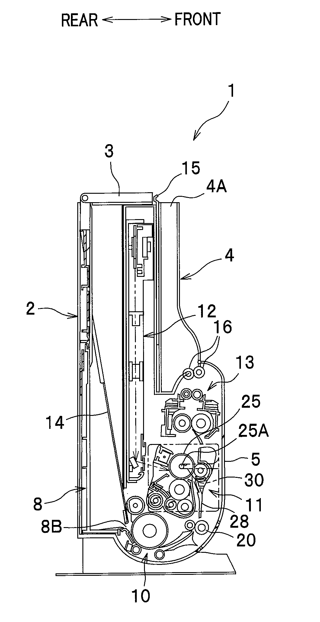
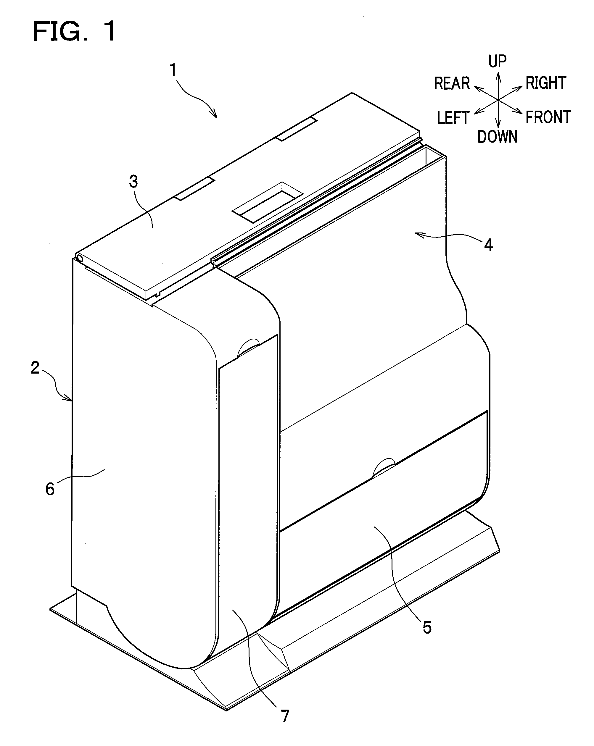
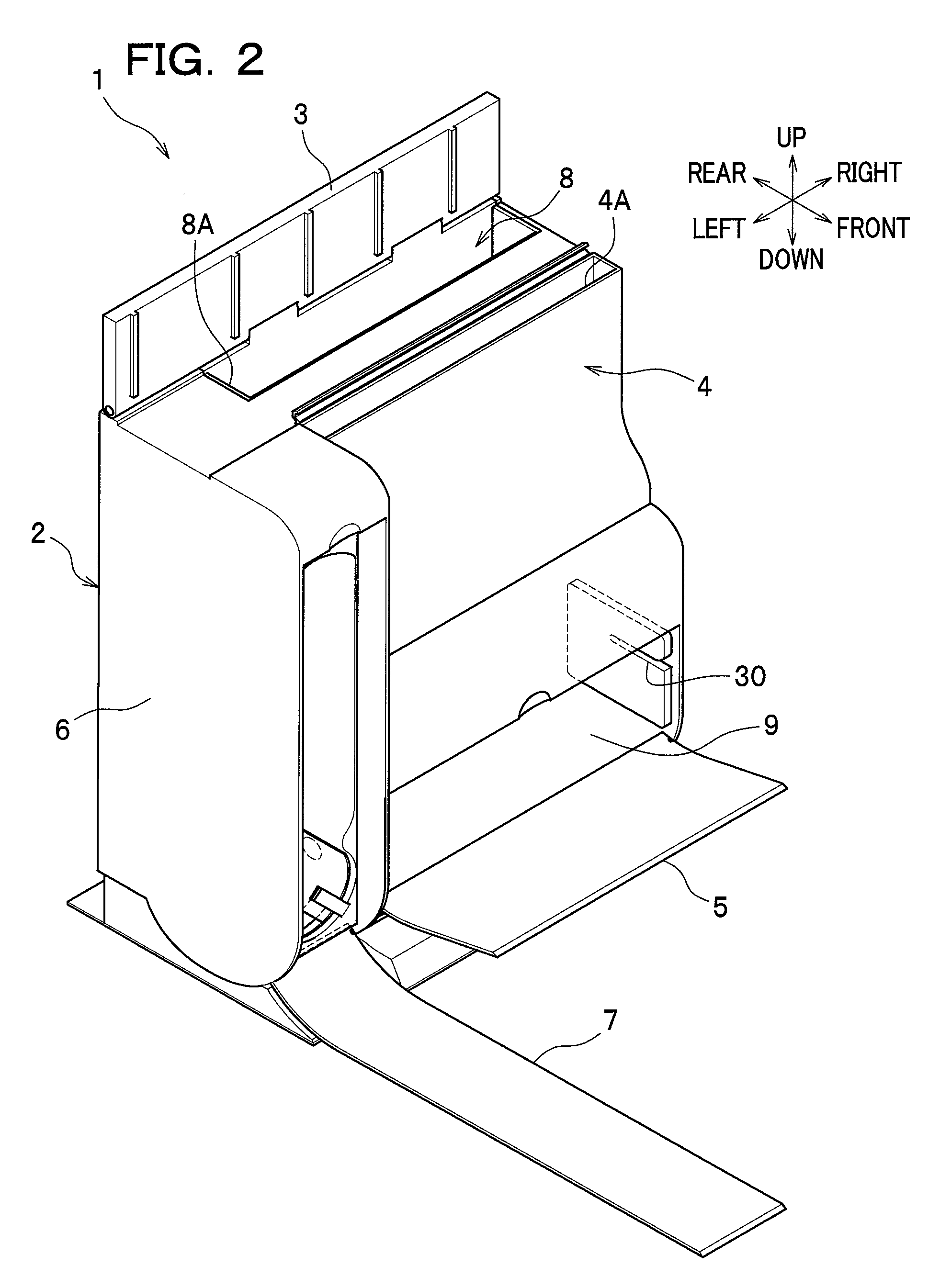
[0028]As seen in FIGS. 1 and 2, an image forming apparatus according to one embodiment of the present invention is provided as an upright-type laser printer 1, which has a relatively short length in the front-back direction compared to the right-and-left direction and the height of which is tall.

[0029]The laser printer 1 has a main body casing 2. A top cover 3 is provided at an upper part of the main body casing 2, and a paper output tray 4 is positioned at a front upper part of the main body casing 2. Provided at a front lower part of the main body casing 2 is a front lower cover 5 which is pivotally supported in the main body casing 2 to open and close a space for attaching a process cartridge 11 to be described later. A toner cartridge storage section 6 in the form of a longitudinal box is positioned at the left side of the main body...


PUM


Abstract

An image forming apparatus includes a recording sheet storage unit for storing recording sheets substantially in an upright position, an image forming unit which forms an image on a recording sheet conveyed from the recording sheet storage unit, and a recording sheet receiving unit for storing the recording sheet conveyed from the image forming unit substantially in an upright position. In this image forming apparatus, a paper conveyance passage extends upward from a lower portion of the recording sheet storage unit toward the recording sheet receiving unit. The image forming unit positioned on the paper conveyance passage comprises a fixing device and a developer unit at least including a developer carrier, and the fixing device is arranged above the developer unit. Further, a developer receptacle for storing developer that is supplied to the image forming unit is arranged adjacent to one longitudinal end of the developer carrier.

Description

CROSS REFERENCE TO RELATED APPLICATIONS[0001]This application claims the foreign priority benefit under Title 35, United States Code, §119(a)-(d) of Japanese Patent Application No. 2007-092115 filed on Mar. 30, 2007 in the Japan Patent Office, the disclosure of which is herein incorporated by reference in its entirety.BACKGROUND OF THE INVENTION[0002]The present invention relates to an image forming apparatus such as a laser printer.[0003]As an image forming apparatus such a laser printer, an upright-type image forming apparatus is generally known. For example, Japanese Laid-open Patent Application No. 2003-302889 discloses such an upright-type image forming apparatus, in which a paper feed tray (recording sheet storage unit) for storing papers as recording sheets and a paper output tray (recording sheet receiving unit) are arranged back and forth with these trays positioned upright.[0004]In this image forming apparatus, the paper feed tray is arranged higher than the paper output t...

Claims


Application Information

Patent Timeline
Patent Type & Authority Applications(United States)
IPC IPC(8): G03G15/00
CPCG03G15/6502G03G15/6552G03G21/1685G03G2215/00383G03G21/1609G03G2215/00004
Inventor SATO, SHOUGOKATAYAMA, SHIGEHARUHANAI, MITSUKO
Owner BROTHER KOGYO KK
Why Eureka
Try Eureka