
Disk array device, operating method thereof and program-storing medium

a technology an operating method, applied in the field of a disk array device, an operating method thereof and a program-storing medium, can solve the problems of increased failure probability reduced redundancy or loss of a hot spare disk, etc., to achieve low failure probability and high failure probability

Inactive Publication Date: 2008-10-02
NEC CORP
View PDF10 Cites 19 Cited by
  • Summary
  • Abstract
  • Description
  • Claims
  • Application Information

AI Technical Summary

Benefits of technology

[0012]The exemplary object of the present invention is to solve the above-mentioned problems. For this purpose, an exemplary object of the present invention is to provide a disk array device, an operating method of the disk array device and a program-storing medium, the disk array device being capable of reliably determining a disk with a high failure probability and removing the disk from the operating RAID to keep the disk in a standby state as a hot spare disk thereby to keep low failure probability of the disk array device, even if the failure probability varies for each hard disk due to the individual specificity such as a hard disk manufacturer, model number or the like.

Problems solved by technology

First, in the above-mentioned typical disk array device, it is not until there occurs a trouble that an operating disk is replaced, so there is a problem that the RAID redundancy is reduced or becomes lost between the time when the trouble arises and the time when the replacement is finished.
There is another problem that a hot spare disk remains in the standby state and still new even though only a hard disk comprising RAID is operated for a longer time and its failure probability becomes higher.
Further, as the disk array devices disclosed in the above-mentioned patent documents 1 and 2 do not consider a variety of failure probabilities among disks based on the individual specificity such as hard disk manufacturer, model number or the like, if the individual specificity is largely different between a failure-prone disk and a failure-proof disk, the hard disk with shorter current-carrying time or shorter cumulative rotation time may fail earlier than the hard disk with longer current-carrying time or longer cumulative rotation time.

Method used


Image

  • Disk array device, operating method thereof and program-storing medium
  • Disk array device, operating method thereof and program-storing medium
  • Disk array device, operating method thereof and program-storing medium

Examples


Embodiment Construction

[0021]With reference to the drawings, an exemplary embodiment to which a disk array device, an operating method of the device, and a program-storing medium according to the present invention are applied will now be described in detail below.

[0022]First description is made about main features of the present exemplary embodiment.

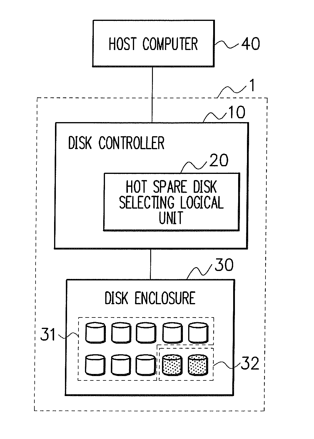
[0023]In this exemplary embodiment, a disk array device including a hot spare disk is characterized in that a disk with the highest failure probability is selected based on S.M.A.R.T. information of each hard disk and changed into a hot spare disk automatically to be kept in a standby state, thereby keeping a low failure probability of the disk array device as a whole.

[0024]Further, as the hot spare disk in the standby state is a disk with the highest failure probability in the disk array device, the hot spare disk is replaced with a new one in regular maintenance thereby keeping a low failure probability of the disk array device as a whole without saving and ...


PUM


Abstract

Even if failure probabilities are different for hard disks due to the individual specificity such as a hard disk manufacturer, model number or the like, a disk with high failure probability is reliably determined and removed from the operating RAID to be kept in a standby state as a hot spare disk, thereby keeping a low failure probability of the disk array device. In order to realize this, the disk array device includes a disk controlling unit for, based on S.M.A.R.T. information of each of the hard disks read by a S.M.A.R.T. information reading unit, assigning a predetermined number of hard disks to the hot spare disk in descending order of failure probability of the hard disks.

Description

[0001]This application is based upon and claims the benefit of priority from Japanese patent application No. 2007-089703, filed on Mar. 29, 2007, the disclosure of which is incorporated herein in its entirety by reference.BACKGROUND OF THE INVENTION[0002]1. Field of the Invention[0003]The present invention relates to a disk array device including a hot spare disk thereby to achieve higher reliability, an operating method of the disk array device and a program-storing medium.[0004]2. Description of the Related Art[0005]Generally, a hot spare disk in a disk array device is in a standby state until a disk comprising RAID (Redundant Array of Inexpensive Disks) fails, and once the disk in operation fails, the disk is replaced with the hot spare disk.[0006]In addition, there is provided a disk array device as a related art of the present invention which performs periodic replacement of each disk with a hot spare disk based on the current-carrying time of the disk. In other words, a disk c...

Claims


Application Information

Patent Timeline
IPC IPC(8): G06F11/00
CPCG06F11/008G06F11/1662G06F11/2094
Inventor FUKUYAMA, OSANORI
Owner NEC CORP
Learn More