Reinforcing Device for Slot Card Reader

a swipe reader and strengthening device technology, applied in the field of swipe reader strengthening devices, can solve the problems of difficult use of joining strengthening strips, non-negligent cost, and relatively complex methods, and achieve the effect of simple assembly and simple design

Active Publication Date: 2008-10-09
BANKS & ACQUIRERS INT HLDG
View PDF3 Cites 0 Cited by
  • Summary
  • Abstract
  • Description
  • Claims
  • Application Information

AI Technical Summary

Benefits of technology

[0009]Another object of the present invention is to provide a swipe reader strengthening device of simple assembly

Problems solved by technology

Such a method is however relatively complex and of non-negligible cos

Method used


Image

  • Reinforcing Device for Slot Card Reader
  • Reinforcing Device for Slot Card Reader

Examples


Embodiment Construction

[0025]For clarity, same elements have been designated with same reference numerals in the different drawings.

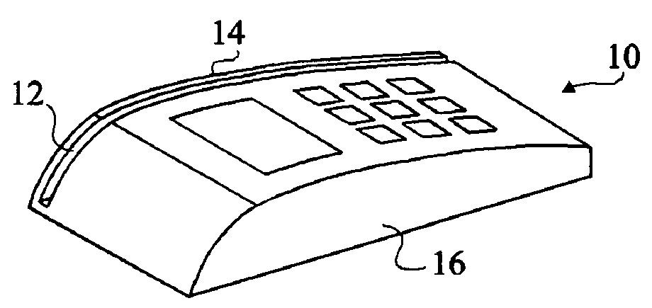
[0026]The present invention consists of a device for strengthening the bottom of a swipe reader slot, which is formed of a wire of substantially circular cross-section made of a low-friction coefficient wear-resisting material, for example, steel. On arranging the wire at the reader slot bottom level, the wire can then easily be deformed to adapt to the slot curvature.

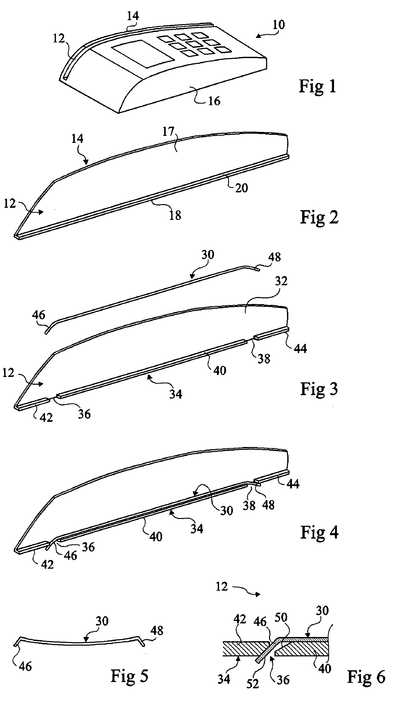
[0027]FIG. 3 shows an example of embodiment of strengthening device 30 according to the present invention and of elements of a swipe reader intended to receive such a device.

[0028]Similarly to FIG. 2, slot 12 is, on one side, delimited by a lateral flange 32 and, on the other side, by parts, not shown, of the card reader. The bottom of slot 12 is delimited by a base 34, which in the shown example is solid with lateral flange 32. However, base 34 may correspond to a part distinct from flange 32. Two notches 36, 3...


PUM


Abstract

A device (30) for strengthening a card reader (10) including a slot (12) at least partly delimited by a base (34) and two lateral walls (17) and extending along a longitudinal direction, the slot being intended to receive a card moving along the longitudinal direction while bearing on the base, the device including a wire (30) of substantially circular cross-section arranged at the level of the base and on which the card is intended to slide.

Description

FIELD OF THE INVENTION[0001]The present invention relates to a device for strengthening a swipe reader. More specifically, the present invention relates to a device for strengthening a swipe reader, of magnetic or optical reader type, in which the swiping of a card in the reader slot is performed manually or in motorized fashion.DISCUSSION OF THE RELATED ART[0002]FIG. 1 schematically shows a conventional example of a magnetic or optical card reader 10. Reader 10 comprises a lateral slot 12 in which a user can swipe a card (not shown). Slot 12 is delimited by a lateral edge 14 of reader 10 and by the body of reader 16. Reader 10 comprises a read head (not shown) capable of reading data stored on the card. It may be a magnetic read head capable of reading data stored in the form of a magnetic strip arranged on the card. It may also be an optical read head capable of reading data stored in the form of a bar code formed on the card.[0003]FIG. 2 schematically shows lateral edge 14 of rea...

Claims


Application Information

Patent Timeline
IPC IPC(8): G06K7/08
CPCG06K13/06G06K13/08
Inventor DUBOIS, ERIC
Owner BANKS & ACQUIRERS INT HLDG
Why Eureka
Try Eureka