Systems for hybrid geometric/volumetric representation of 3d objects

Active Publication Date: 2008-10-09
3D SYST INC
12 Cites 12 Cited by

AI-Extracted Technical Summary

Problems solved by technology

However, geometric representations are not as effective for modeling more organic, realistic, and/or complex shapes.
However, voxel-based models are not as effective as geometric models at representing objects with sharp edges.
Traditional modeling systems do not combine both volumetric and geometric representations, and do not have the ability to perfor...

Benefits of technology

[0006]The invention provides a system for modeling three-dimensional objects using a hybrid geometric/volumetric representation, wherein sharp edges are created by a geometric r...

Abstract

The invention provides a system for modeling three-dimensional objects using hybrid geometric/volumetric representation, wherein sharp edges are created by a geometric representation that is connected to the volumetric representation. The system creates, maintains, and updates the hybrid representation according to user input. The system also provides for conversion of the hybrid representation into either a wholly geometric representation or a wholly volumetric representation, as may be needed for output to a given device, such as a display device, a printer, and/or a fabricating device.

Application Domain

Additive manufacturing apparatusInput/output processes for data processing +1

Technology Topic

Computer visionComputer graphics (images) +4

Image

  • Systems for hybrid geometric/volumetric representation of 3d objects
  • Systems for hybrid geometric/volumetric representation of 3d objects
  • Systems for hybrid geometric/volumetric representation of 3d objects

Examples

  • Experimental program(1)

Example

[0032]Throughout the description, where processes, systems, and methods are described as having, including, or comprising specific steps and/or components, it is contemplated that, additionally, there are processes, systems, and methods according to the present invention that consist essentially of, or consist of, the recited steps and/or components.
[0033]It should be understood that the order of steps or order for performing certain actions is immaterial so long as the invention remains operable. Moreover, two or more steps or actions may be conducted simultaneously.
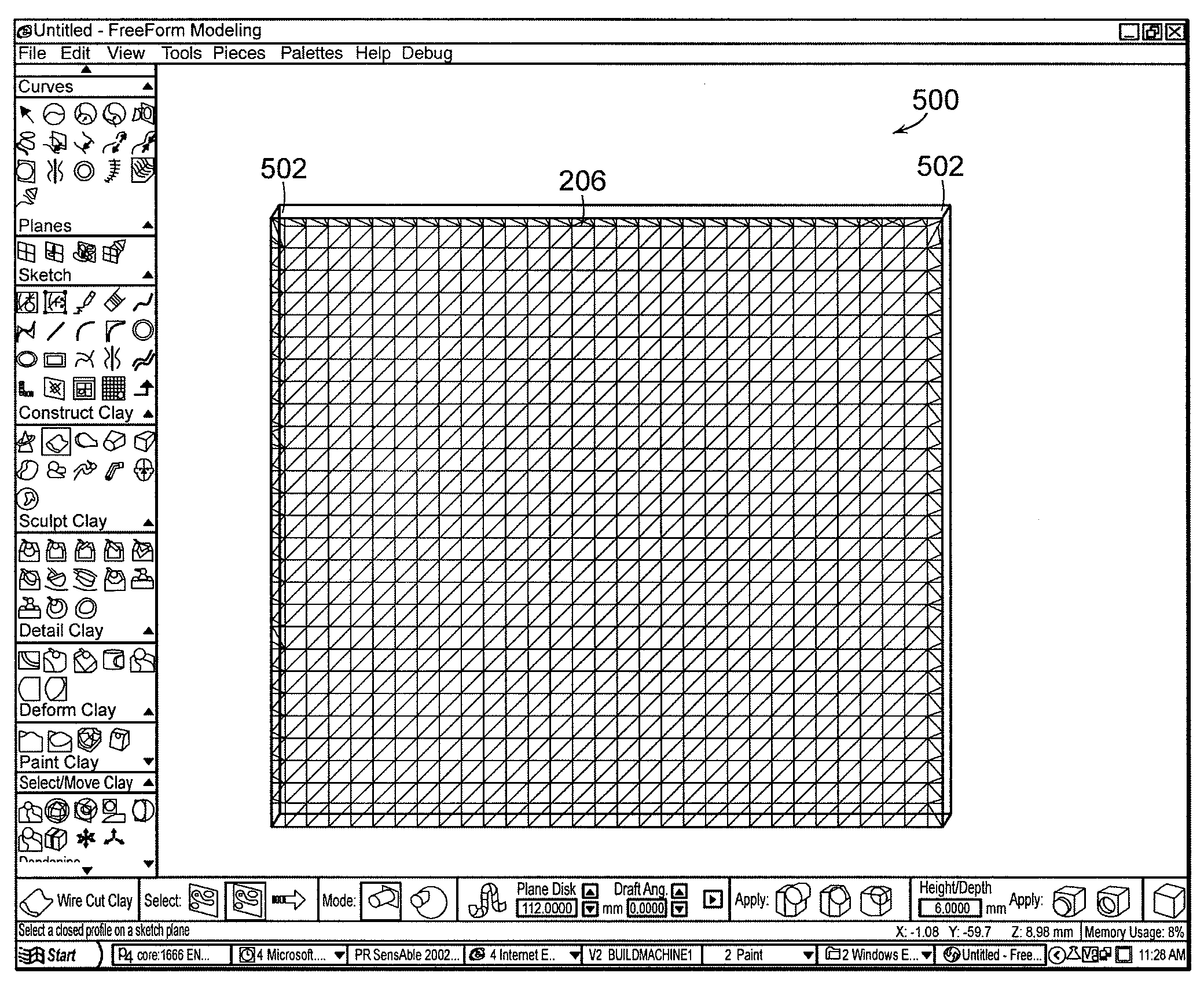
[0034]The systems may include a PHANTOM® force-feedback device, for example, the PHANTOM® force-feedback device manufactured by SensAble Technologies, Inc., of Woburn, Mass., providing the operator with 3D navigation and the ability to use his/her sense of touch to model quickly and accurately with virtual clay. The operator can create original 3D models or use the systems with STL data from scanners or existing medical and dental software, for example. For example, CT/MRI scans (or any other scans) that have been converted to STL data can also be used. Files can be exported for Rapid Prototyping (RP) or milling, and CAD/CAM, for example.
[0035]Voxels are found herein to be superior for sculpting and carving virtual objects with organic shapes, such as teeth, bridges, implants, and the like. The system provides a hybrid representation, for example, a combination of voxel-based representation with one or more other types of data representation, for example, geometric representation (e.g., point clouds, meshes, NURBS surfaces, polygons, polyhedra, and/or the like), such that the benefit of voxel representation in sculpting and carving can be achieved, while the benefit of the geometric data representation is additionally achieved.
[0036]In certain embodiments, the system provides a mixed representation in an editing model, for example, using NURBS curves, polygonal objects such as triangles, and voxels, together in the editing model, to represent the object. This goes beyond simply import/export of polygonal, geometric, and NURBS items into/from a purely voxel-based editing model. Here, the editing model itself comprises the mixed representation, allowing seamless creation, editing, interaction, and/or manipulation by the user.
[0037]U.S. Pat. No. 6,084,587, commonly-owned by the assignee of this patent application and incorporated by reference herein in its entirety, describes user selection of both geometric and volumetric representations in a set of sub-constructs. U.S. Pat. No. 7,102,635, commonly-owned by the assignee of this patent application and incorporated by reference herein in its entirety, describes conversion between surface representation and volumetric representation. The system of the present application further describes seamless user interaction, creation, and/or editing of a mixed mode representation. In one example, the mixed mode allows a deficiency in one mode (e.g., inability of a voxel-based representation to model a sharp edge) to be overcome by another mode (e.g., representation of the sharp edge by precise geometric objects such as a NURBS curve).
[0038]One particular embodiment of the system for hybrid geometric/volumetric representation of a 3D object is a system that adds a sharp edge to a volumetrically-defined (e.g., voxel-based) solid using a geometric curve (e.g., NURBS curve) and polygons. U.S. Pat. No. 7,102,635 describes a voxel-based modeling approach (see, for example, column 17 to column 18). A voxel-based model of a solid has “facets” at its corners, which result from the discretization of model data when converted to voxels.
[0039]This is seen, for example, in the screenshot 200 of FIG. 2, at the corners 202 of the virtual object. The virtual object seen in FIG. 2 is a purely voxel-based representation produced from a “wirecut” operation (a rectangle constructed from virtual clay based on a planar rectangular sketch curve). A square “sharpening” curve (e.g., the NURBS curve defining the edge 206 in the plane of the mesh 204 of FIG. 2) can be used as a guide. Polygons, for example, triangles, are added to the model to fill in the gap between the discrete voxel representation (the virtual clay surface) and the desired NURBS curve (the “sharpening” curve) defining the edge 206. In certain embodiments the desired NURBS curve (the “sharpening” curve) will be automatically derived from the surface using another method. For example, a user may implement a virtual 3D painting tool to mark a region of the virtual object for sharpening. A NURBS curve may be derived by the software based on the surface in the marked region. Alternatively, the user may simply select one or more objects in a virtual environment to be automatically sharpened according to embodiments of the invention.
[0040]FIG. 3 shows a screenshot 300 viewing the square-shaped end of the virtual object of FIG. 2. FIG. 4 shows a screenshot 400 showing the sharpening curve 206 and the beveled edges of the virtual object, with the bevels seen most clearly at the corners 202. FIG. 5 shows a screenshot 500 of the geometric representation portion of the eventual hybrid model, consisting of the polygons 502 filling in the gap between the discrete voxel representation (the virtual clay surface) and the desired NURBS curve (the “sharpening” curve) defining the edge 206. FIG. 6 shows a screenshot 600 of the hybrid representation of the 3D object including the voxel-based representation portion and the geometric representation portion. FIG. 7 shows a screenshot 700 of the hybrid representation from a different angle. FIG. 8 shows a screenshot 800 of the hybrid representation with the sharpening curves hidden from view (to better view the clay).
[0041]The volumetric and geometric portions of the hybrid model can be interacted with, edited, sculpted, and/or otherwise manipulated seamlessly, without having to combine them in a post-process. Thus, a user can “feel” both the volumetric portion (e.g., the voxel-based portion) and the geometric portion (e.g., the triangles forming the edges). When the model is exported to STL, the voxels can be translated to triangles (or other polygons), for example, and the added triangles (the geometric portion) are also included in the exported data, maintaining the sharp edge.
[0042]In the example above, the purposes is to create an edge whose “sharpness” with respect to its resolution is higher than that of the quantized volumetrically-defined (e.g., voxel-based) solid to which the edge is attached. The user may have one or more ways to define the resolution-independent edge (e.g., by selecting a band of the volumetric solid with a virtual tool, such as a 3D painting tool, to derive an edge from a NURBS curve positioned just above the surface of the volumetric solid).
[0043]The system then connects the curve to the volumetrically-defined solid by a series of polygons (e.g. triangles) that tessellate the three-dimensional area connecting the geometric edge to the surface of the volumetrically-defined solid. In one embodiment, the invention generates triangular polygons by projecting a point from the curve to a triangular mesh representation of the voxel surface, splitting the mesh with a new point, “pulling” that point to the curve and adding the triangular polygons which ensue. Other embodiments employ different triangular polygon generation mechanisms depending on the desired cross-sectional shape of the sharp edge. The tessellating triangles form a polygonal mesh creating a closed surface.
[0044]The user may select any region of a resolution-independent geometry, resolution-dependent geometry, or quantified volumetric (e.g. voxel-based) representation for conversion to another geometry type. The system can stitch the geometry together accordingly so that the desired output representation remains a closed surface. The user has independent control over the type of boundary transition between the different types of surfaces/volumes.
[0045]The system can convert the hybrid representation created by the above-described operations into a uniform representation consisting of resolution-independent geometry, resolution-dependent geometry or quantized volumetric representation for output purposes consistent with the expectation of a specific output device.
[0046]In one embodiment, the system generates triangular polygons by projecting a point from the curve to a voxel surface, splitting the surface with a new point, “pulling” that point to the curve and adding the triangular polygons which ensue. Other embodiments employ different generation mechanisms depending on the desired cross-sectional shape of the sharp edge.
[0047]The boundary regions between the hybrid representations are transition regions. These boundary regions can be indicated by NURBS curves that fit to the surface regardless of the representation. The user can specify the width of the boundary region using either a fixed width for the entire boundary or variable width using secondary curves or control points. The user then specifies (or the software may determine) what type of geometric transition should occur, for example: a) a sharp transition; b) a transition that shares a common tangent; or c) a transition that shares a common center of curvature.
[0048]In certain embodiments, the invention allows the user to convert a hybrid of a resolution-independent geometric representation (e.g. NURBS ) and a quantified volumetric representation into a single resolution-independent geometric representation. In this case, the resolution-independent representation (e.g., NURBS) is sliced by the user-defined boundary curve. The volumetric portion of the model is converted to the resolution-independent representation (e.g., NURBS representation), fit with the same boundary curve. Depending on the type of transition specified, the surfaces will have either a sharp or a gradual transition at the boundary curve. If the transition is gradual, additional transition geometry (e.g., a strip of NURBS patches) will be built to fit the geometry together. In either case the resulting geometry will be water tight.
[0049]In certain embodiments, the invention allows the user to convert a hybrid of a resolution-dependent geometric representation (e.g. triangular mesh) and a quantified volumetric representation into a single resolution-dependent geometric representation. In this case, a user-defined poly line curve will trim the resolution dependent representation. The voxel representation will be converted into a resolution-dependent geometric representation using an algorithm such as Marching Cubes. Both representations will be modified to fit to the bounding poly line. If a smoother transition is specified, the vertices of the transition area will be relaxed to produce the desired transition.
[0050]In certain embodiments, the invention allows the user to convert a voxel model into a NURBS representation providing a best fit to the surface. In other embodiments, the user is given control as to what degree of tolerance is used to match the NURBS representation to the voxel representation. In this case using a tool similar to 3d paint, a color can be applied to the voxel representation indicating how fine an amount of detail is converted into the NURBS representation. The same method can be used to specify a region to be very smooth. Like wise the addition of 3d NURBS curves for sharpening can be used for NURBS boundaries in the converted region.
[0051]In certain embodiments, the system allows the user to convert the hybrid representation to a wholly quantized representation by specifying the degree of quantization. This correlates to the size of the voxels used.
[0052]FIG. 9 shows a system for one embodiment of the invention, including a haptic interface device 910, modeling application 912, and graphics display 914 in electrical communication with each other. The modeling application 912 includes a haptic rendering process 916, a virtual tool and object interaction process 918, a virtual object modification process 920, a graphics process 922, and a 3-D printer 923 all in electrical communication with each other.
[0053]A user of the system uses the haptic interface device 910 to interact with the virtual object receiving force feedback produced by the haptic rendering process 916 and viewing graphics rendered by the graphics process 922 on a graphic display 914. The user may also output the virtual object, or a surface representation of it, to a 3-D printer 923 to produce an actual 3-D physical model of the virtual object.
[0054]In one embodiment, a “process”, as referred to in FIG. 1, is a software process executing on a hardware microprocessor. All the processes may execute on one microprocessor, or in other embodiments, one or more processes may execute on different microprocessors, which are linked by buses, cables, local networks, wide area networks, or global computer networks, such as the Internet.
[0055]The modeling application 912 is viewed in FIG. 1 as a software application executing on one computer system. In another embodiment, the modeling application 912 executes on one or more computer systems connected by a communications device, such as a bus, cable, or network connection. In an alternate embodiment, the modeling application is a hardware device, such as an ASIC (application specific integrated circuit), and one or more processes of the application are implemented on one or more ASIC devices. In a further embodiment, the modeling application 912 is implemented as one or more objects, which may execute on one or more computer systems.
[0056]The modeling application 912 is not required to include all of a haptic rendering process 916, an interaction process 918, a modification process 920, and a graphics process 922, but may instead exclude one or more of these processes. In one embodiment, the modeling application 912 includes the haptic rendering process 916 and the graphics process 922.
[0057]In one embodiment, the invention is implemented using an object-oriented approach. The haptic rendering process 916 and other processes are implemented as software objects. In another embodiment, the virtual object and a virtual (software) tool are implemented as software objects and perform one or more of the functions of the haptic rendering process 916. In one embodiment, a virtual tool is a software object that performs such functions as determining if contact has occurred with a virtual object and determining the surface direction vector.
[0058]In one embodiment, the virtual object and the virtual tool are implemented as software objects in the C++ programming language. In other embodiments, the virtual object and virtual tool are implemented using an object-oriented programming language other than C++.
[0059]In one embodiment, the modeling application is (or includes) a computer program stored on a computer readable storage media, such as a CD disc, diskette, tape, or other media. In another embodiment, the modeling application is (or includes) a computer program distributed over a computer-readable propagated signal, such as a program distributed over the Internet.
Haptic Interface Device
[0060]In one embodiment, the system includes a haptic interface system, as shown in FIG. 9, including the haptic interface device 910 and the haptic rendering process 916 which generates a virtual object of the virtual environment to be “touched” and determines the results of the interaction (discussed in more detail below). The haptic interface device 910 is a tactile or force-feedback device which provides the touch sensations of interacting with virtual objects to a user of the system. Some haptic interface devices 910 include an electromechanical linkage which can exert a controllable force on a user's hand. See, for example, U.S. Pat. No. 5,625,576 issued to Thomas H. Massie and J. Kenneth Salisbury, Jr., the disclosure of which is herein incorporated by reference in its entirety. As used herein, “haptic rendering” refers to the creation of a virtual environment with which a user can interact through the sense of touch. The term “haptic rendering process”916 refers to the computer program which generates the haptic aspects of the virtual environment and determines the forces to be applied to a user through a haptic interface. The haptic rendering process 916 generates haptic representations of virtual objects in the virtual environment.
[0061]FIG. 10 is a schematic perspective view 1000 of an exemplary six degree of freedom force reflecting haptic interface device 910 that can be used in accordance with one embodiment of the invention. The interface 910 can be used by a user to provide input to a device, such as a computer, and can be used to provide force feedback from the computer to the user. The six degrees of freedom of interface 910 are independent.
[0062]The interface 910 includes a housing 1012 defining a reference ground, six joints or articulations, and six structural elements. A first powered tracked rotary element 1014 is supported by the housing 1012 to define a first articulation 1016 with an axis “A” having a substantially vertical orientation. A second powered tracked rotary element 1018 is mounted thereon to define a second articulation 1020 with an axis “B” having a substantially perpendicular orientation relative to the first axis, A. A third powered tracked rotary element 1022 is mounted on a generally outwardly radially disposed extension 1024 of the second element 1018 to define a third articulation 1026 having an axis “C” which is substantially parallel to the second axis, B. A fourth free rotary element 1028 is mounted on a generally outwardly radially disposed extension 1030 of the third element 1022 to define a fourth articulation 1032 having an axis “D” which is substantially perpendicular to the third axis, C. A fifth free rotary element 1034 is mounted on a generally outwardly radially disposed extension 1036 of the fourth element 1028 to define a fifth articulation 1038 having an axis “E” which is substantially perpendicular to the fourth axis, D. Lastly, a sixth free rotary user connection element 1040 in the form of a stylus configured to be grasped by a user is mounted on a generally outwardly radially disposed extension 1042 of the fifth element 1034 to define a sixth articulation 1044 having an axis “F” which is substantially perpendicular to the fifth axis, E. The haptic interface of FIG. 10 is fully described in commonly-owned U.S. Pat. No. 6,417,638, issued on Jul. 9, 2002, which is incorporated by reference herein in its entirety. Those familiar with the haptic arts will recognize that there are many different haptic interfaces that convert the motion of an object under the control of a user to electrical signals, many different haptic interfaces that convert force signals generated in a computer to mechanical forces that can be experienced by a user, and haptic interfaces that accomplish both results.
[0063]The computer used in systems described herein can be a general purpose computer, such as a commercially available personal computer that includes a CPU, one or more memories, one or more storage media, one or more output devices, such as a display 914, and one or more input devices, such as a keyboard. The computer operates using any commercially available operating system, such as any version of the Windows™ operating systems from Microsoft Corporation of Redmond, Wash., or the Linux™ operating system from Red Hat Software of Research Triangle Park, N.C. In some embodiments, a haptic device such as the interface 910 is present and is connected for communication with the computer, for example with wires. In other embodiments, the interconnection can be a wireless or an infrared interconnection. The interface 910 is available for use as an input device and/or an output device. The computer is programmed with software including commands that, when operating, direct the computer in the performance of the methods of the invention. Those of skill in the programming arts will recognize that some or all of the commands can be provided in the form of software, in the form of programmable hardware such as flash memory, ROM, or programmable gate arrays (PGAs), in the form of hard-wired circuitry, or in some combination of two or more of software, programmed hardware, or hard-wired circuitry. Commands that control the operation of a computer are often grouped into units that perform a particular action, such as receiving information, processing information or data, and providing information to a user. Such a unit can comprise any number of instructions, from a single command, such as a single machine language instruction, to a plurality of commands, such as a plurality of lines of code written in a higher level programming language such as C++. Such units of commands are referred to generally as modules, whether the commands include software, programmed hardware, hard-wired circuitry, or a combination thereof. The computer and/or the software includes modules that accept input from input devices, that provide output signals to output devices, and that maintain the orderly operation of the computer. In particular, the computer includes at least one data input module that accepts information from the interface 910 which is indicative of the state of the interface 910 and its motions. The computer also includes at least one module that renders images and text on the display 914. In alternative embodiments, the computer is a laptop computer, a minicomputer, a mainframe computer, an embedded computer, or a handheld computer. The memory is any conventional memory such as, but not limited to, semiconductor memory, optical memory, or magnetic memory. The storage medium is any conventional machine-readable storage medium such as, but not limited to, floppy disk, hard disk, CD-ROM, and/or magnetic tape. The display 914 is any conventional display such as, but not limited to, a video monitor, a printer, a speaker, an alphanumeric display, and/or a force-feedback haptic interface device. The input device is any conventional input device such as, but not limited to, a keyboard, a mouse, a force-feedback haptic interface device, a touch screen, a microphone, and/or a remote control. The computer can be a stand-alone computer or interconnected with at least one other computer by way of a network, for example, a client/server network. This may be an internet connection.
Equivalents
[0064]While the invention has been particularly shown and described with reference to specific preferred embodiments, it should be understood by those skilled in the art that various changes in form and detail may be made therein without departing from the spirit and scope of the invention as defined by the appended claims. Insofar as this is a provisional application, what is considered applicants' invention is not necessarily limited to embodiments that fall within the claims below.

PUM

no PUM

Description & Claims & Application Information

We can also present the details of the Description, Claims and Application information to help users get a comprehensive understanding of the technical details of the patent, such as background art, summary of invention, brief description of drawings, description of embodiments, and other original content. On the other hand, users can also determine the specific scope of protection of the technology through the list of claims; as well as understand the changes in the life cycle of the technology with the presentation of the patent timeline. Login to view more.
Why Eureka
Try Eureka