
Medical device with position sensor having core with high permeability material for determining location coordinates of a portion of the medical device

Inactive Publication Date: 2006-01-31
BIOSENSE
View PDF28 Cites 43 Cited by
  • Summary
  • Abstract
  • Description
  • Claims
  • Application Information

AI Technical Summary

Benefits of technology

[0020]In an alternative embodiment of the position sensor according to the present invention, the material of the core comprises a copper, nickel, and iron alloy (CuNiFe). In another embodiment of the position sensor according to the present invention, the material of the core comprises an iron, chrome, and cobalt alloy. These alternative embodiments for the core material also ensure accuracy within approximately 0.5 mm for the position sensor according to the present invention.
[0022]Both the position sensor and the medical device and position sensor combination, both in accordance with the present invention, are used in conjunction with a position and orientation system that maintains accuracy even at high temperatures.

Problems solved by technology

However, such chips suffer from nonlinearities, saturation effects, hysteresis and temperature drifts.
It has always been believed that smaller coils of the same type would not provide acceptable performance and are also hard to manufacture.
Additionally, given these fixed size limitations, no sensor coils have been developed that have an outer diameter less than 0.6 mm.
However, for both types of core materials, the sensor coils utilizing such core material would be generally limited to the outer diameter minimum dimension requirements described above.
Because the axes of the coils need to be generally mutually orthogonal in order to achieve accurate position sensing in all six dimensions, it is not possible to make the diameter of the assembly much smaller.

Method used


Image

  • Medical device with position sensor having core with high permeability material for determining location coordinates of a portion of the medical device
  • Medical device with position sensor having core with high permeability material for determining location coordinates of a portion of the medical device
  • Medical device with position sensor having core with high permeability material for determining location coordinates of a portion of the medical device

Examples


Embodiment Construction

[0040]For purposes of this disclosure, the terms “sensor coil”, “coil”, “position sensor” and “location sensor” have the same meaning and are used interchangeably. A position sensor is a sensor that provides location information in the form of signals that determine position and / or orientation coordinates of the position sensor in the manner described above.

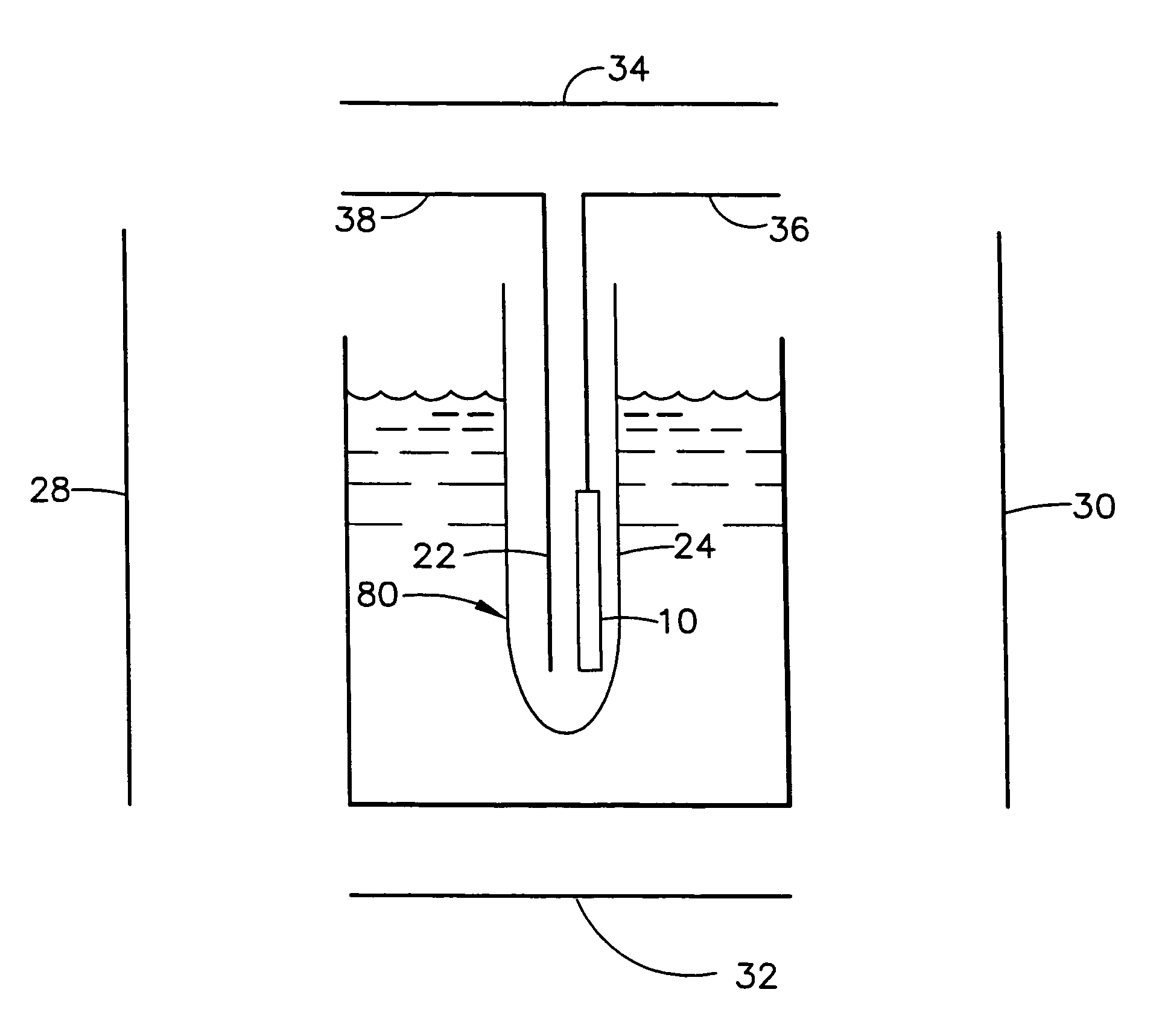
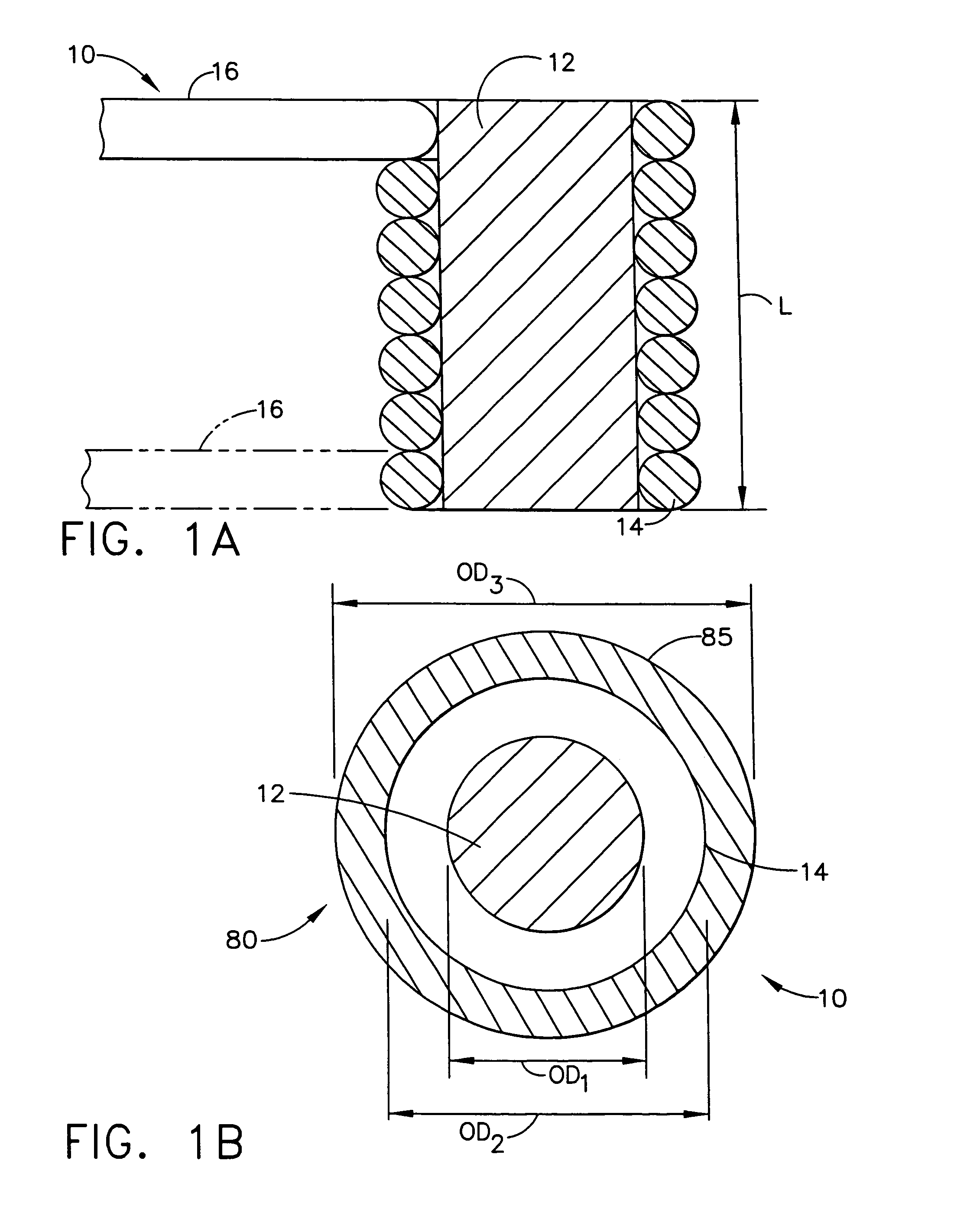
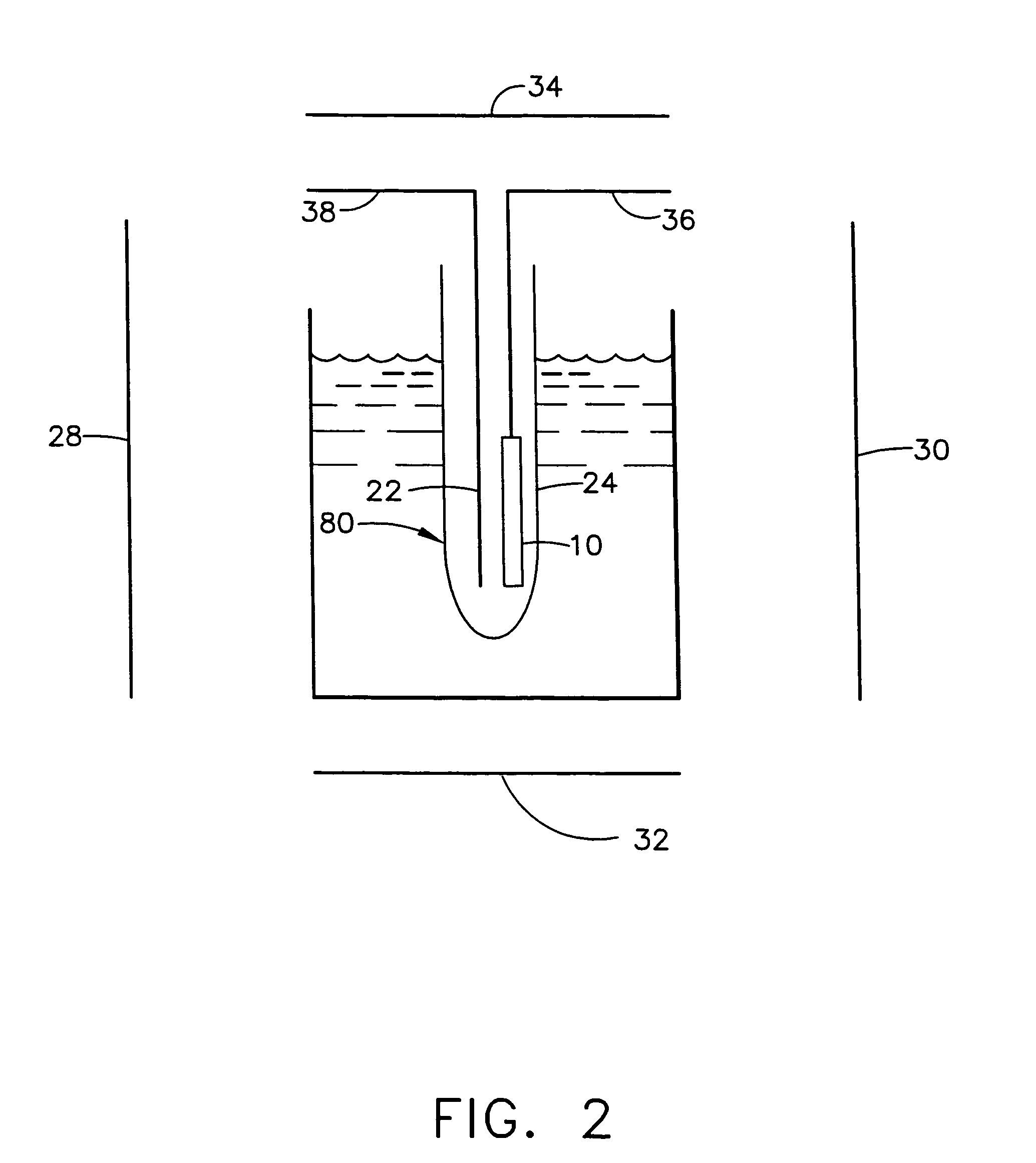
[0041]The present invention, as best illustrated in FIGS. 1A and 1B, show a position sensor according to the present invention comprising a sensor coil 10 having a core 12 made of Wiegand effect material, which is described in greater detail below, and a winding (in the form of copper wire) attached to or circumferentially wrapped around the core 12. The sensor coil 10 is particularly useful as a position sensor for a medical device 80 as shown in FIG. 1B. As mentioned previously, the sensor coil 10 is used as a position sensor for determining location information in the form of position coordinate and / or orientation coordinates....


PUM


Abstract

A medical location system includes a medical device having a body and a position sensor at a portion of the body. The position sensor has a core made of a Wiegand effect material and a winding circumferentially positioned around the core. The position sensor provides signals that are used to determine temperature at the position sensor and location information of the portion of the body of the medical device. A signal processor is coupled to receive the signals from the position sensor and the signal processor determines the temperature at the position sensor and location information of the portion of the body of the medical device based on the signals received from the position sensor.

Description

FIELD OF THE INVENTION[0001]The present invention relates generally to object tracking systems, and specifically to position sensors having high sensitivity at high temperatures for tracking the position and orientation of a medical device.BACKGROUND OF THE INVENTION[0002]In many medical procedures, devices, such as probes, endoscopes, catheters, stents and tags / markers are inserted into a patient's body. Such devices are used for a large variety of procedures including irreversible surgical actions, such as ablation and taking of tissue samples. Therefore, it is necessary to have accurate information on the position and orientation of the probe within the patient's body.[0003]Electromagnetic position determining systems provide a convenient method of receiving accurate information on the position and orientation of intra-body objects, and allow accurate tracking of these objects. Such systems are described for example in U.S. Pat. Nos. 5,558,091, 5,391,199 and 5,443,489, and in Int...

Claims


Application Information

Patent Timeline
IPC IPC(8): G01B7/004A61B5/05G01R33/00A61B1/00A61B5/01A61B5/06G01B7/00G01B7/30G01D5/20G01R33/02
CPCA61B5/06G01D5/2006G01B7/30G01B7/003A61B5/062
Inventor GOVARI, ASSAF
Owner BIOSENSE
Learn More