Numerical analysis mesh generating method and apparatus

a numerical analysis and generating method technology, applied in the field of numerical analysis mesh generating methods and apparatuses, can solve the problems of methods having difficulty in generating large-scale numerical analysis meshes, foregoing conventional methods provide the capability of generating large-scaled meshes, and need a considerable long time in generating such meshes, so as to reduce the time of generating meshes, and reduce the size of the mesh

Inactive Publication Date: 2008-10-09
HITACHI LTD
View PDF7 Cites 23 Cited by
  • Summary
  • Abstract
  • Description
  • Claims
  • Application Information

AI Technical Summary

Benefits of technology

[0019]The mesh to be located inside the geometry model is not necessarily the regular mesh. That is, instead of the regular mesh, it is possible to fit the pre-created tetrahedral mesh in the triangular mesh on the surface of geometry model and then to use the result as the inner mesh. Moreover, by locating a space with a half of a target element dimension as a minimum between the boundary of geometry model and the inner mesh, it is possible to generate an excellent mesh in the portion closer to the surface.
[0020]According to the invention, since the mesh is sequentially generated, what is to be meshed is only the shell-like gap portion, so that the area to be meshed becomes quite small. This leads to noticeably reducing the meshing time. Concretely, it is grasped that the meshing time is reduced into one-fifth or less in some models.
[0021]Further, about the regular mesh portion, the data about only the surface of the mesh portion is stored in a memory. Hence, the memory capacity required when generating a mesh is made smaller.

Problems solved by technology

However, the foregoing conventional methods provide a capability of generating a large-scaled mesh but need a considerably long time in generating such a mesh.
Those methods thus have difficulty in generating a large-scaled numerical analysis mesh.
The Voxel mesh also has difficulties of rugged surface and limited range of analysis.
This method, however, may make the mesh near the surface of geometry model irregular.

Method used


Image

  • Numerical analysis mesh generating method and apparatus
  • Numerical analysis mesh generating method and apparatus
  • Numerical analysis mesh generating method and apparatus

Examples


Embodiment Construction

[0036]Hereafter, one embodiment of the present invention will be described with reference to FIGS. 1 to 11.

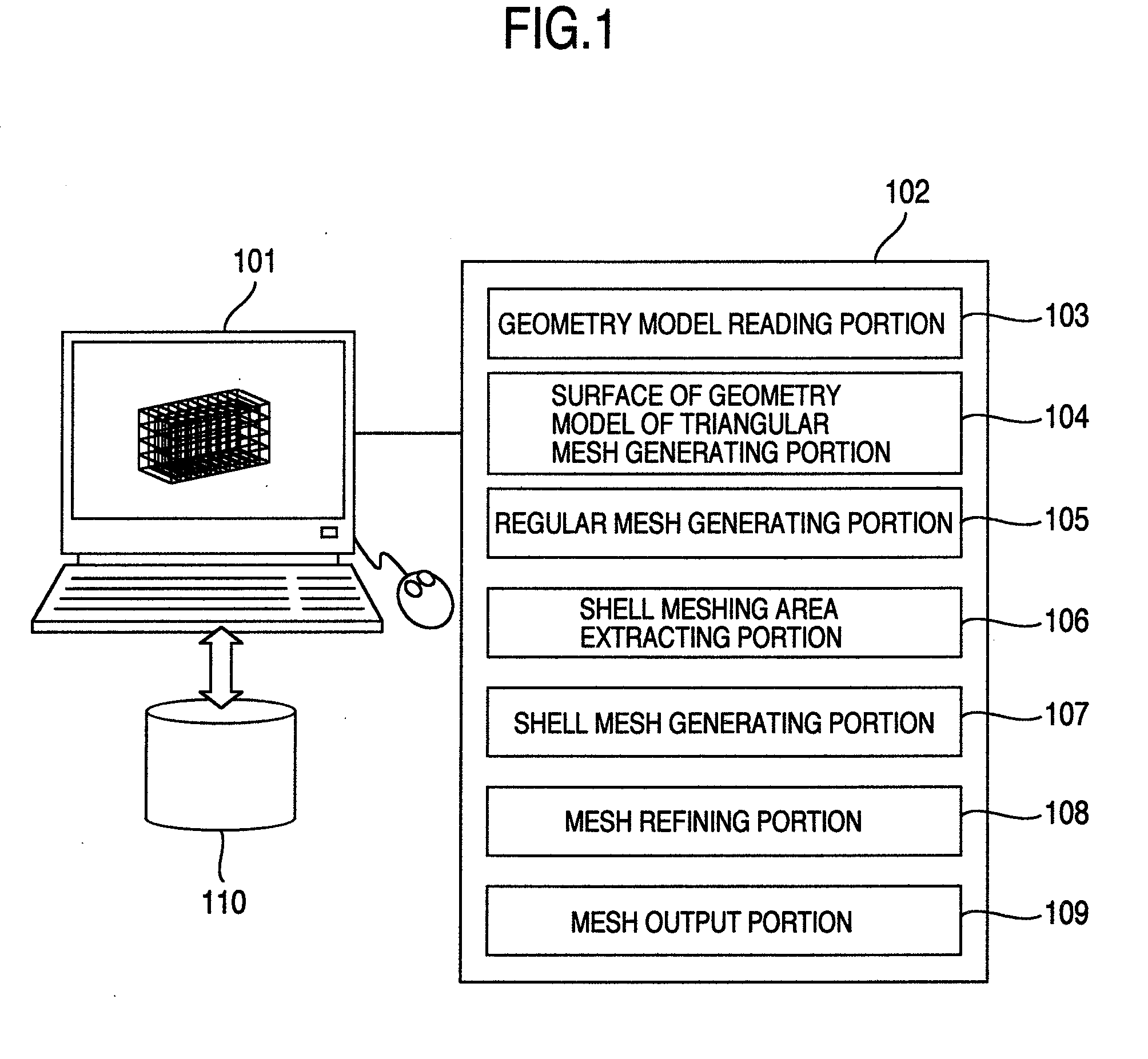
[0037]FIG. 1 is a model diagram showing an exemplary arrangement of a large-scaled numerical analysis mesh generating apparatus according to the embodiment of the invention.

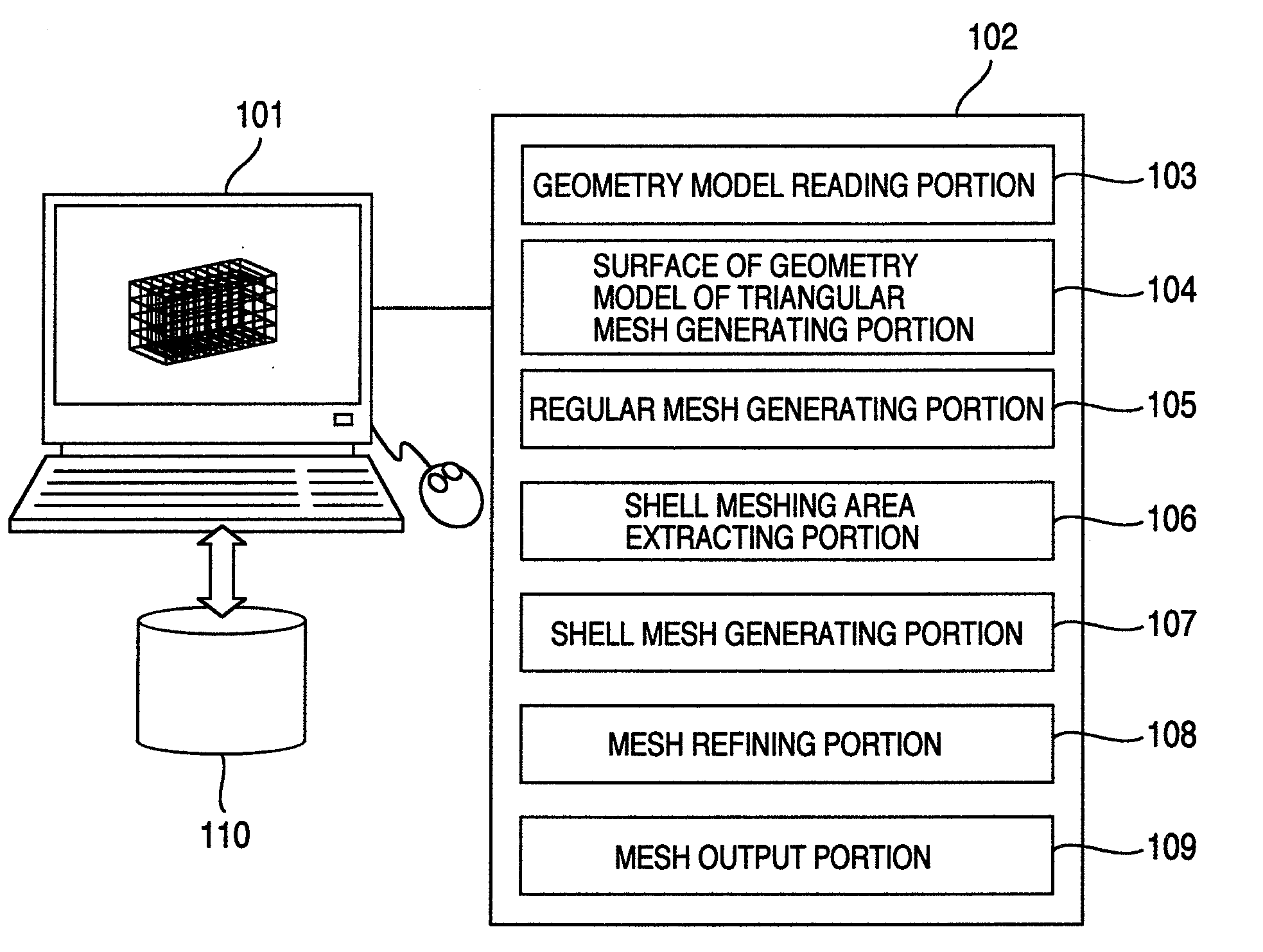
[0038]As shown in FIG. 1, the large-scaled numerical analysis mesh analyzing apparatus is arranged to have a computer 101 and a large-scaled numerical analysis mesh generating program 102. The computer 101 is arranged to have a CPU, a storage unit, an I / O unit including a keyboard and a display, an external storage unit 110, and so forth.

[0039]Further, the large-scaled numerical analysis mesh generating program 102 is configured of a geometry model reading portion 103, a surface of geometry model triangular mesh generating portion 104, a regular mesh generating portion 105, a shell meshing area extracting portion 106, a shell mesh generating portion 107, a mesh refining portion 108, and a mesh output portion...


PUM


Abstract

The triangular mesh generating portion divides the surface of geometry model to be meshed in a meshed manner according to a target element dimension and generates a triangular mesh on the surface of geometry model. The regular mesh generating portion assumes a shaped parallelpiped enclosing the shape to be meshed. The parallelpiped is divided in a meshed manner by the hexahedral element whose distance between the nodes has the substantially same density as the triangular mesh on the surface. The resulting regular mesh located inside the triangular mesh on the surface of geometry model is divided into a tetrahedral meshed manner. The shell meshing area extracting portion extracts a shell-like space between the inner tetrahedral mesh and the triangular mesh on the surface of geometry model. The shell mesh generating portion generates the tetrahedral mesh in the overall shape to be meshed.

Description

BACKGROUND OF THE INVENTION[0001]1. Field of the Invention[0002]The present invention pertains to a technology of CAE (Computer Aided Engineering) which aides in designing and developing a product through the use of a computer, and more particularly to an apparatus and a method for generating a numerical analysis mesh which are arranged to quickly generate the numerical analysis mesh.[0003]2. Description of the Related Art[0004]As an analysis simulation computer environment including such as a super computer or a PC (Personal Computer) cluster is becoming highly enhanced, analysis of an overall product and multi-physical analysis are being expected more and more. These sorts of analyses essentially need to generate tens to hundreds of millions of analysis meshes. Hence, the current purpose of this technology is the way of reducing a time taken in generating a large-scaled mesh.[0005]As a method of automatically generating a three-dimensional numerical analysis mesh, there have well ...

Claims


Application Information

Patent Timeline
Patent Type & Authority Applications(United States)
IPC IPC(8): G06T17/20
CPCG06T17/20
Inventor YOKOHARI, TAKASHINISHIGAKI, ICHIRO
Owner HITACHI LTD
Why Eureka
Try Eureka