
DTV receiving system and method of processing DTV signal

Inactive Publication Date: 2008-10-09
LG ELECTRONICS INC
View PDF6 Cites 32 Cited by
  • Summary
  • Abstract
  • Description
  • Claims
  • Application Information

AI Technical Summary

Benefits of technology

[0008]Another object of the present invention is to provide DTV systems and methods of processing television signals that can enhance the receiving performance of a digital broadcast receiving system by performing additional encoding on mobile service data and by transmitting the processed data to the receiving system.
[0009]A further object of the present invention is to provide DTV systems and methods of processing television signals that can also enhance the receiving performance of a digital broadcast receiving system by inserting known data already known in accordance with a pre-agreement between the receiving system and the transmitting system in a predetermined area within a data area.

Problems solved by technology

Therefore, the receiving performance of the digital broadcast receiving system may be deteriorated in a poor channel environment.
Particularly, since resistance to changes in channels and noise is more highly required when using portable and / or mobile broadcast receivers, the receiving performance may be even more deteriorated when transmitting mobile service data by the VSB transmission mode.

Method used


Image

  • DTV receiving system and method of processing DTV signal
  • DTV receiving system and method of processing DTV signal
  • DTV receiving system and method of processing DTV signal

Examples


first embodiment

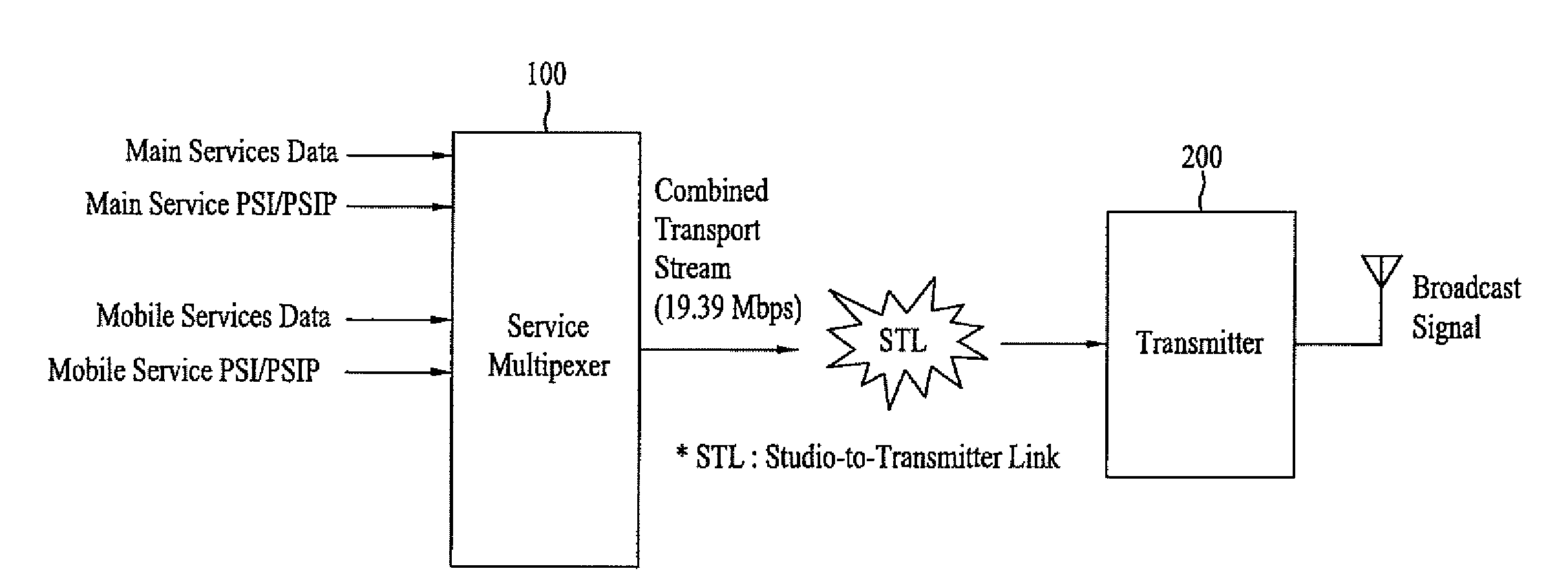
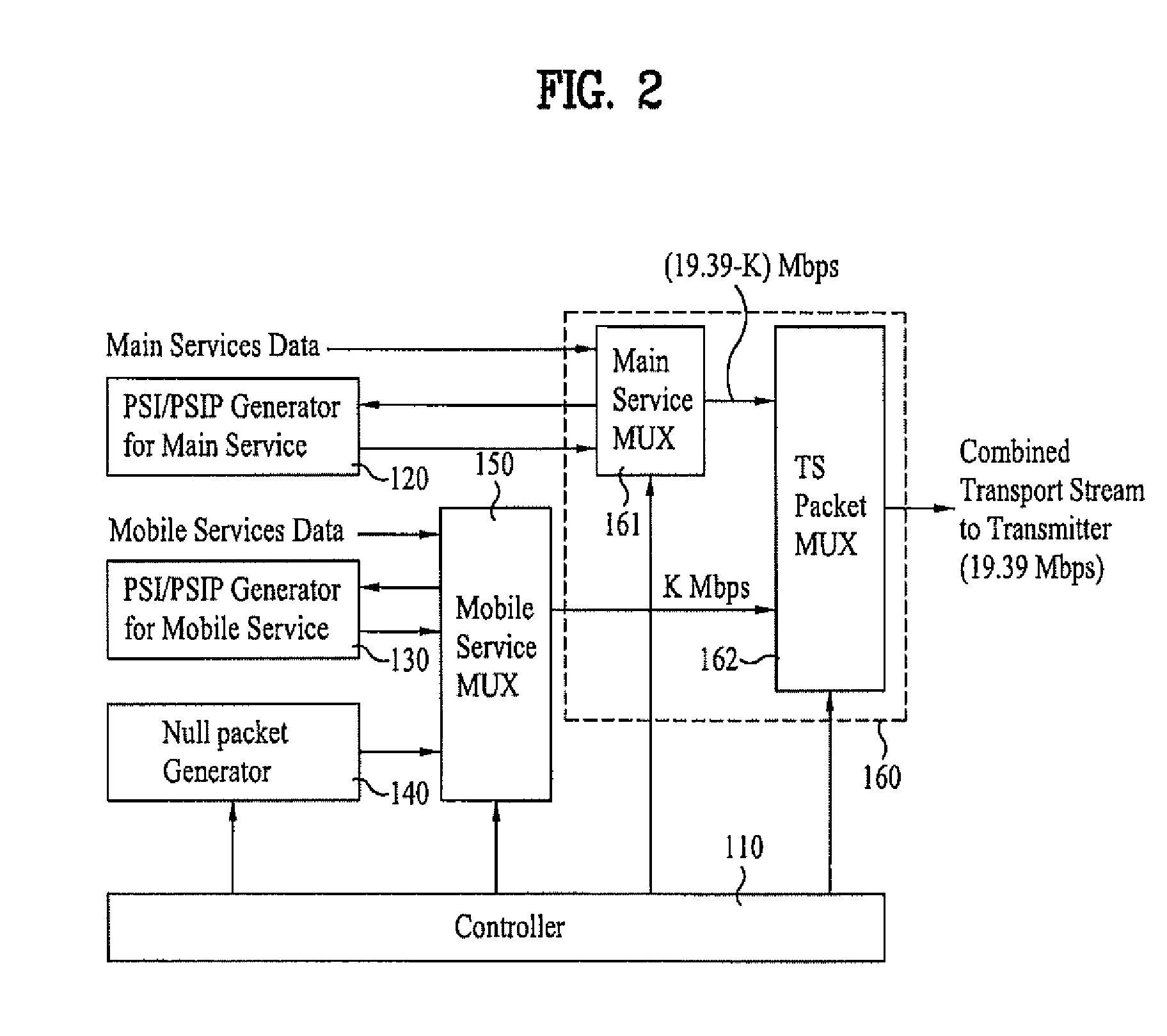
[0167]FIG. 18 illustrates a schematic diagram of the group formatter 304 receiving the transmission parameter and inserting the received transmission parameter in region A of the data group according to the present invention. Herein, the group formatter 304 receives mobile service data from the block processor 303. Conversely, the transmission parameter is processed with at least one of a data randomizing process, a RS frame encoding process, and a block processing process, and may then be inputted to the group formatter 304. Alternatively, the transmission parameter may be directly inputted to the group formatter 304 without being processed with any of the above-mentioned processes. In addition, the transmission parameter may be provided from the service multiplexer 100. Alternatively, the transmission parameter may also be generated and provided from within the transmitter 200. The transmission parameter may also include information required by the receiving system in order to rec...

second embodiment

[0171]Meanwhile, when known data generated from the group formatter in accordance with a pre-decided rule are inserted in a corresponding region within the data group, a transmission parameter may be inserted in at least a portion of a region, where known data may be inserted, instead of the known data. For example, when a long known data sequence is inserted at the beginning of region A within the data group, a transmission parameter may be inserted in at least a portion of the beginning of region A instead of the known data. A portion of the known data sequence that is inserted in the remaining portion of region A, excluding the portion in which the transmission parameter is inserted, may be used to detect a starting point of the data group by the receiving system. Alternatively, another portion of region A may be used for channel equalization by the receiving system.

[0172]In addition, when the transmission parameter is inserted in the known data region instead of the actual known...

third embodiment

[0178]Meanwhile, the transmission parameter may also be inserted in the field synchronization segment region and then transmitted. FIG. 21 illustrates a block diagram showing the synchronization multiplexer being expanded in order to allow the transmission parameter to be inserted in the field synchronization segment region. Herein, a signaling multiplexer 261 is further included in the synchronization multiplexer 260. The transmission parameter of the general VSB method is configured of 2 fields. More specifically, each field is configured of one field synchronization segment and 312 data segments. Herein, the first 4 symbols of a data segment correspond to the segment synchronization portion, and the first data segment of each field corresponds to the field synchronization portion.

[0179]One field synchronization signal is configured to have the length of one data segment. The data segment synchronization pattern exists in the first 4 symbols, which are then followed by pseudo rand...


PUM


Abstract

A digital television (DTV) receiving system includes a tuner, a demodulator, a known data detector, an equalizer, a transmission detector, and a block decoder. The tuner receives a DTV signal having a data frame in which main and mobile service data are multiplexed. The demodulator demodulates the DTV signal, and the known data detector detects known data included in the mobile service data. The equalizer equalizes the demodulated DTV signal using the detected known data, and the transmission parameter detector detects an error correction mode from the equalized DTV signal. Finally, the block decoder decodes the equalized DTV signal for error correction using the detected error correction mode.

Description

[0001]This application claims the benefit of the Korean Patent Application No. 10-2007-0034021, filed on Apr. 6, 2007, which is hereby incorporated by reference as if fully set forth herein. Also, this application claims the benefit of U.S. Provisional Application No. 60 / 911,506, filed on Apr. 12, 2007 which is hereby incorporated by reference.BACKGROUND OF THE INVENTION[0002]1. Field of the Invention[0003]The present invention relates to a digital television (DTV) systems and methods of processing television signals.[0004]2. Discussion of the Related Art[0005]The Vestigial Sideband (VSB) transmission mode, which is adopted as the standard for digital broadcasting in North America and the Republic of Korea, is a system using a single carrier method. Therefore, the receiving performance of the digital broadcast receiving system may be deteriorated in a poor channel environment. Particularly, since resistance to changes in channels and noise is more highly required when using portable...

Claims


Application Information

Patent Timeline
IPC IPC(8): H04N5/455
CPCH04N21/235H04N21/23611H04N21/2362H04N21/2365H04N19/89H04N21/435H04N21/4382H04N21/4425H04N21/4347H04N7/015
Inventor LEE, HYOUNG GONCHOI, IN HWANKWAK, KOOK YEONKIM, JONG MOONSONG, WON GYUKIM, BYOUNG GILLKIM, JIN WOO
Owner LG ELECTRONICS INC
Learn More