
IEEE 1149.1 and p1500 test interfaces combined circuits and processes

a combined circuit and test interface technology, applied in the direction of logic circuit coupling/interface arrangement, generating/distributing signals, instruments, etc., can solve the problems of high overhead and test complexity of circuit area, prohibitive routing of 14 test signals to a core, and high overhead of wire routing area

Active Publication Date: 2008-10-09
TEXAS INSTR INC
View PDF6 Cites 14 Cited by
  • Summary
  • Abstract
  • Description
  • Claims
  • Application Information

AI Technical Summary

Benefits of technology

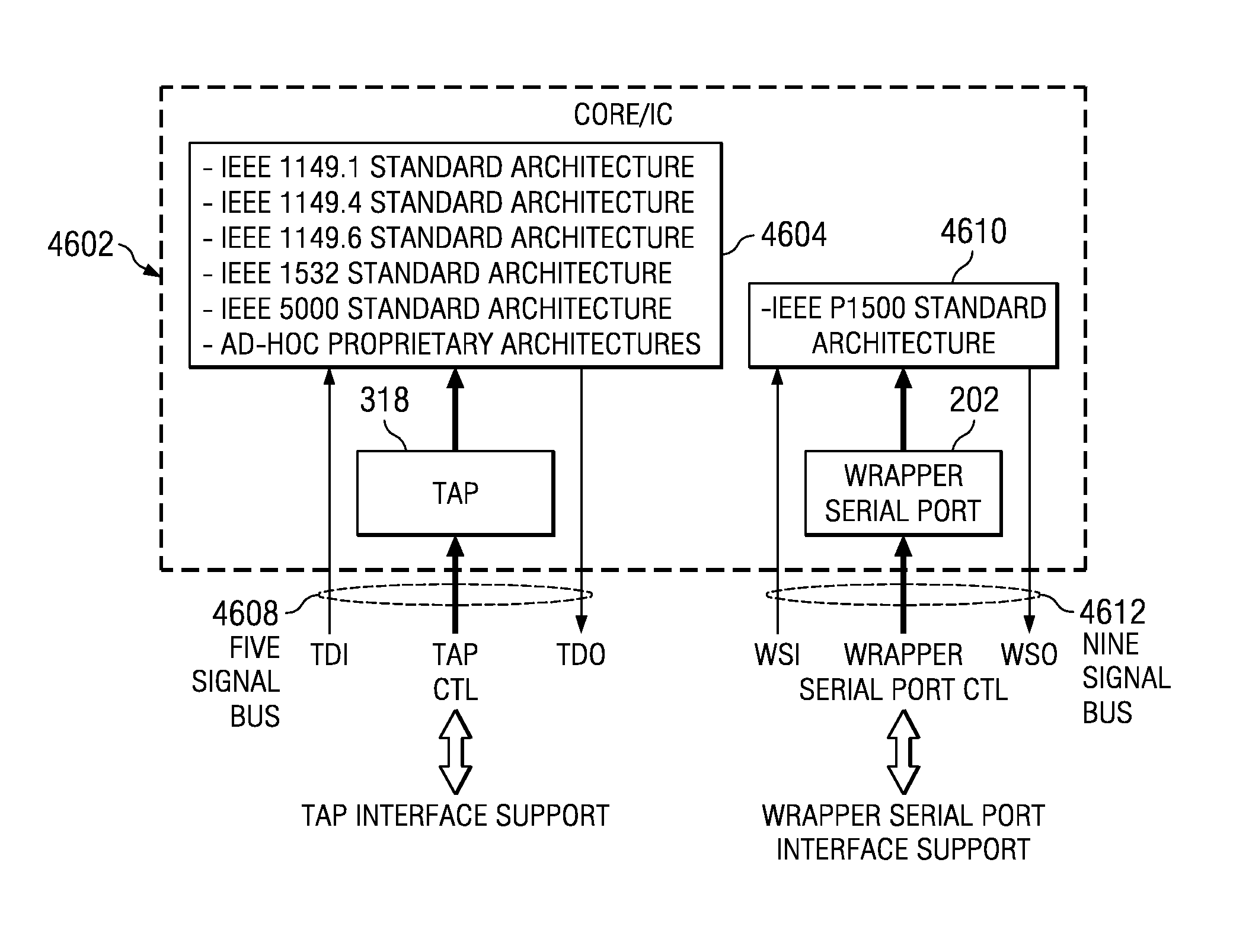
[0056]In accordance with the present disclosure, first and second embodiments are provided to remedy the described problems of having two separate standards implemented in cores and / or ICs. The first embodiment is an approach whereby a TAP 318 is allowed to commandeer control from the WSP 202 such that the P1500 architecture, normally controlled by the WSP, is rendered controllable by the TAP. The second embodiment is an approach whereby; (1) the TAP and WSP based architectures are merged together such that the sharing of the previously described architectural elements are possible, and (2) the TAP and WSP test interfaces are merged into a single optimized test interface that is operable to perform all operations of each separate test interface.

Problems solved by technology

Having to include both test standards in ICs can be costly in circuit area overhead and test complexity.
In some ICs the routing of 14 test signals to a core can be prohibitive, especially if multiple cores exist with each potentially needing its own bus of 14 test signals.
Thus having two separate standards implemented in a core, each with separate test bus interfaces, can lead to problems related to wire routing area overhead.
Further, it is clear that due to the nature of the non-dedicated WSP 9 pin interface, the range of WSP interface support will be most likely limited to testing.
Lastly, having both TAP and WSP based domains in cores can lead to IC wire routing and density problems.

Method used


Image

  • IEEE 1149.1 and p1500 test interfaces combined circuits and processes
  • IEEE 1149.1 and p1500 test interfaces combined circuits and processes
  • IEEE 1149.1 and p1500 test interfaces combined circuits and processes

Examples


second embodiment

Detailed Description of the Second Embodiment

[0167]FIG. 49 illustrates a circuit 4902 which represents architectural modifications to circuit 4602 according to the second embodiment. The modifications include: (1) combining the architectures 4604 and 4610 of circuit 4602 to form a single merged architecture 4904, (2) eliminating the WSP 202 test interface of circuit 4602, and (3) adding an auxiliary test control (ATC) bus of signals 4908 and combining those signals with the TAP 318 test bus 4608 to form a merged test interface 4906 which provides control and access to the merged architecture 4904.

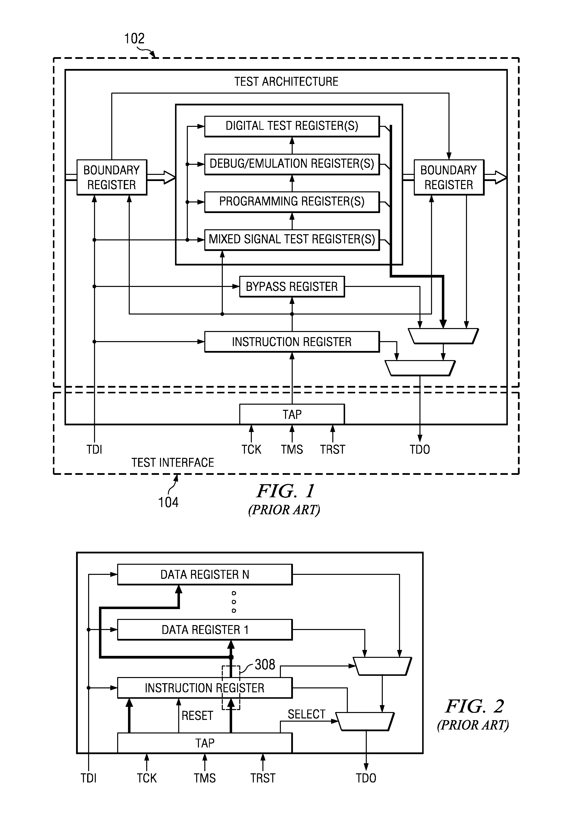
[0168]FIG. 50 illustrates the merged test interface 4906 and merged architecture 4904 in more detail. As seen, the merged test interface 4906 and architecture 4904 is identical to the TAP based architecture of FIG. 2, with the exception that the merged architecture 4904 includes an additional gating circuit 5004. The gating circuit 5004 receives input 5006 from the data register control bus...


PUM


Abstract

In a first embodiment a TAP of IEEE standard 1149.1 is allowed to commandeer control from a WSP of IEEE standard P1500 such that the P1500 architecture, normally controlled by the WSP, is rendered controllable by the TAP. In a second embodiment (1) the TAP and WSP based architectures are merged together such that the sharing of the previously described architectural elements are possible, and (2) the TAP and WSP test interfaces are merged into a single optimized test interface that is operable to perform all operations of each separate test interface. One approach provides for the TAP to maintain access and control of the TAP instruction register, but provides for a selected data register to be accessed and controlled by either the TAP+ATC or by the discrete CaptureDR, UpdateDR, TransferDR, ShiftDR, and ClockDR WSP data register control signals.

Description

RELATED PATENTS / APPLICATIONS[0001]This application is a divisional of prior Application No. 11 / 051,707, filed Feb. 4, 2005, currently pending;[0002]Which claims the benefit under 35 USC 119(e) of prior-filed provisional application 60 / 603,292, filed Aug. 20, 2004.[0003]This application is related to nonprovisional patent application 09 / 845,562, filed Apr. 30, 2001 and nonprovisional patent application Ser. No. 10 / 874,054, filed Jun. 21, 2004, which are incorporated herein by reference.TECHNICAL FIELD OF THE DISCLOSURE[0004]This disclosure relates in general to integrated circuit design and testing, and in particular to an improved test interface and architecture that may be included in intellectual property core circuits and integrated circuits.BACKGROUND OF THE DISCLOSURE[0005]Today large system-on-chips (SOC) are being designed that include a myriad of different types of complex functional circuits. Standardized IC test interfaces and architectures are needed for testing these fun...

Claims


Application Information

Patent Timeline
Patent Type & Authority Applications(United States)
IPC IPC(8): G01R31/28
CPCG01R31/318594G01R31/318536G01R31/28G01R31/3177G06F13/4282G06F13/287H03K19/017509G06F1/12G01R31/31713G01R31/31724G01R31/31727
Inventor WHETSEL, LEE D.
Owner TEXAS INSTR INC
Learn More