Delay Budget Allocation with Path Trimming

a technology of delay and budget allocation, applied in the field of delay, can solve the problems of increasing methodology, impracticality, and only working properly of devices, and achieve the effects of increasing costs, impracticality, and increasing costs

Active Publication Date: 2008-10-09
KK TOSHIBA +1
View PDF1 Cites 5 Cited by
  • Summary
  • Abstract
  • Description
  • Claims
  • Application Information

AI Technical Summary

Benefits of technology

[0009]One or more of the problems outlined above may be solved by the various embodiments of the invention. Broadly speaking, the invention includes systems a

Problems solved by technology

The devices will only work properly if data and control signals are available when they are needed.
The performance of the device may also be affected by the allocation of this delay budget to subcomponents of the circuitry along the path.
As the complexity of the circuits grew, however, this methodology became increasingly expensive and impractical because of the required

Method used


Image

  • Delay Budget Allocation with Path Trimming
  • Delay Budget Allocation with Path Trimming
  • Delay Budget Allocation with Path Trimming

Examples


example 1

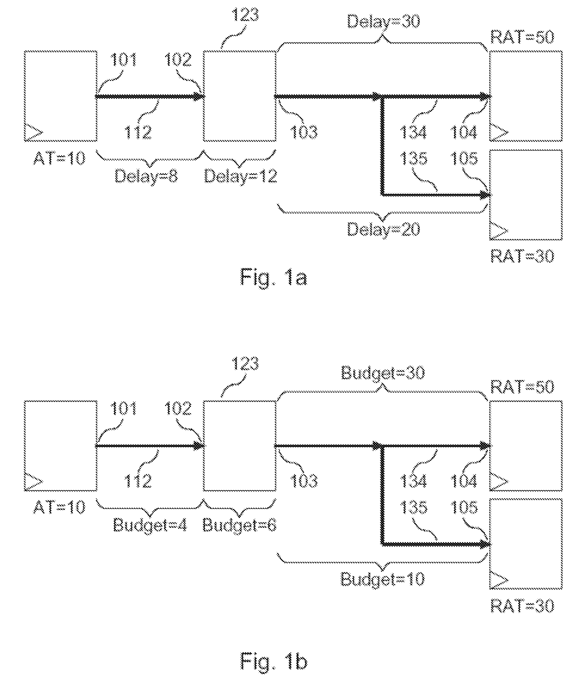
[0089]FIG. 7 includes the delays “D(e)” and delay budgets “B(e)” of an example in accordance with one embodiment. In this example, Dmin(e)=0 is assumed for each timing edge e.

[0090]First, process Backward is executed for each timing node (Line [400]). When v=V1, there are no incoming edges. Hence, Bset(V1)={(10,0)}. When v=V2, the initial value of Bset(V2) is Ø since there exists an incoming edge e=(V1,V2)=E12. Let u denote the head of this edge, which is node V1 (Line [504]). Execute Backward(V1) (Line [505]). Since node V1 is already visited, it simply comes back without doing anything (Line [500]). Set (SB,TB)=(10,0), which is the only element in Bset(V1) (Line [506]). Since Dmin(e)=0, SB is not updated, and remains 10 (Line [508]). Since D(E12)=8, TB becomes 0+(8−0)=8 (Line 509). Bset(V2) is now {(10,8)} (Line [510]). Since there is only one element in Bset(V2), nothing is done from line [513] through [527]. Similarly, Backward procedure gives Bset(V3)={(10,20)}, Bset(V4)={(10,5...

example 2

[0093]FIG. 8 illustrates an example in accordance with one embodiment. In this more complex example, it is also assume Dmin(e)=0 for each timing edge e. The pairs of numbers surrounded by parentheses represent the results of backward or forward tracing, as appropriate. Among them, those attached to timing nodes V02, V01, and V03 represent the contents of Bset(v) after applying Backward(V03), and those attached to timing nodes V04, V05, V06, V07, V08, and V09 represent the contents of Fset(u) after applying Forward(V04). A pair of numbers struck through, such as at node V08, represents a trimmed backward or forward path after applying path trimming (lines [513] through [527] in FIG. 5 and lines [613] through [627] in FIG. 6). Note that there are only 2 pairs at V04. Without path trimming, there would normally be 4 pairs. There are only 2 pairs due to the path trimming at V08 and V04. Since node V04 uses the results of node V08, the path trimming has a multiplying effect. When the siz...


PUM


Abstract

Systems and methods for determining delay budget allocations for circuit elements. One embodiment comprises a method including defining timing edges and corresponding timing paths in an integrated circuit design, and determining delay budget allocations for each of the edges based on required arrival time and design slack (S,T) pairs associated with the different timing paths. The required arrival time is a maximum time when associated with forward paths, and a minimum time when associated with backward paths. (S,T) pairs associated with some timing paths are discarded (i.e., the corresponding timing paths are trimmed) to reduce the complexity of the delay budget allocation computations. Remaining (S,T) pairs are used to determine scaling factors for significant timing paths through the edges. The smallest of the scaling factors for each edge can be multiplied by an initial delay associated with the edge to produce a delay budget allocation associated with the edge.

Description

BACKGROUND[0001]1. Field of the Invention[0002]The invention relates generally to the design of integrated circuits and more particularly to systems and methods for providing delay budget assignments that meet circuit timing requirements.[0003]2. Related Art[0004]As digital devices (e.g., integrated circuits) have become more complex, including more and more electronic components, better tools are needed to design these devices. In particular, the efficiency of the tools is in need of improvement just to handle the ever increasing size of the design problems.[0005]Part of the task of designing a digital device is to determine the timing for the device's circuits. The devices will only work properly if data and control signals are available when they are needed. For instance, circuitry that receives certain data at time t1 may have to process the data and generate a corresponding output signal by time t2 so that it can be used by another part of the device. A proposed design for the ...

Claims


Application Information

Patent Timeline
IPC IPC(8): G06F17/50
CPCG06F17/5031G06F30/3312
Inventor UCHINO, TAKUNG, ALVAN
Owner KK TOSHIBA
Why Eureka
Try Eureka