Fuel cutoff valve

a technology of fuel cutoff valve and float, which is applied in the direction of valve operating means/releasing devices, mechanical equipment, transportation and packaging, etc., can solve the problems of large number of parts, difficult practice in integral formation of elastic impact pieces in the lower portion of floats made of resin, and noise, etc., to reduce the impact noise of the first, improve the noise reduction effect, and reduce the vibration of the first float 51

Inactive Publication Date: 2008-10-16
TOYODA GOSEI CO LTD
View PDF0 Cites 17 Cited by
  • Summary
  • Abstract
  • Description
  • Claims
  • Application Information

AI Technical Summary

Benefits of technology

The invention described in this patent text has several technical effects. First, a seat member is installed in the upper part of a first float to absorb energy associated with vibration, reducing impact noise. The seat member is easily attached to the first float without mispositioning. Second, the seat member is a separate component from the first float, allowing for optimal vibration absorption and easy attachment to different types of fuel cutoff valves. Third, a bottom support portion in the lower cover reduces the size of the gap with the seat member, allowing for a smaller valve support element. Fourth, the bottom support portion guides the wall surface of the buoyancy chamber, preventing tilting. Fifth, the upper end of the bottom support portion prevents the seat member from sticking to it.

Problems solved by technology

The technical problem addressed in this patent relates to reducing noise caused by repeated movement and collisions between the floating mechanism of a fuel cutoff valve and the surrounding components during vehicle operation. Existing solutions involving adding elastic pieces or absorbing members have either been difficult to implement or resulted in increased complexity.

Method used


Image

  • Fuel cutoff valve
  • Fuel cutoff valve
  • Fuel cutoff valve

Examples


Embodiment Construction

(1) General Configuration of Fuel Cutoff Valve

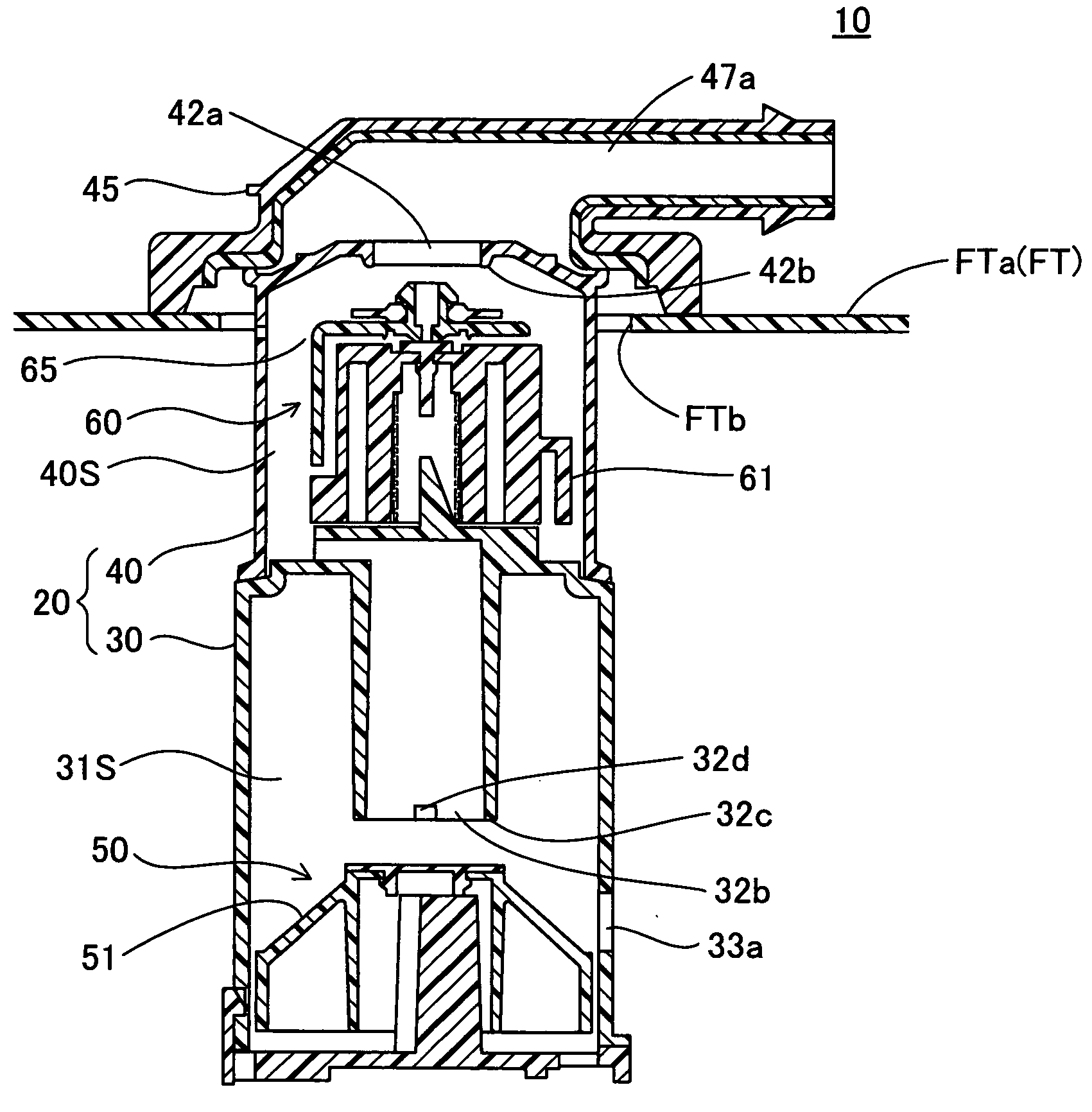
[0029]FIG. 1 is a sectional view depicting a fuel cutoff valve 10 pertaining to a first embodiment of the present invention. A fuel tank FT depicted in FIG. 1 is formed of composite resin material that includes polyethylene on the surface, and has a mounting hole FTb formed in the tank upper wall FTa. The fuel cutoff valve 10 is mounted on the tank upper wall FTa with its lower part inserted in the mounting hole FTb. The fuel cutoff valve 10 is designed to regulate outflow to the canister as well as activate the auto-stop function when the fuel in the fuel tank FT has risen to a first level FL1 during fueling, as well as to prevent overfilling when the fuel level exceeds a second level FL2.

(2) Configuration of Fuel Cutoff Valve 10 Parts

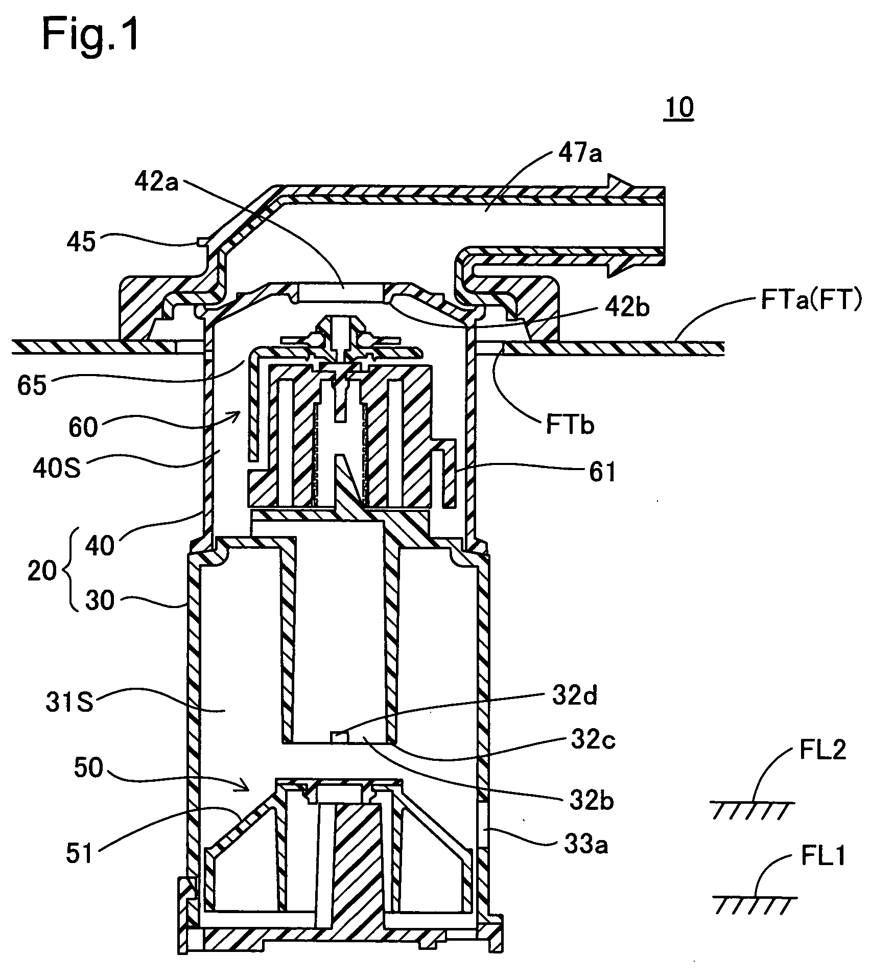
[0030]In FIG. 1, the fuel cutoff valve 10 includes as principal components a casing 20, a first valve mechanism 50, and a second valve mechanism 60. The casing 20 includes a first casing unit 30 and a seco...


PUM


Abstract

The fuel cutoff valve has a first valve mechanism inside a first valve chamber of a casing. In the first valve mechanism, a seat member installs on the upper part of a first float. The seat member has a seat portion which seats in a first seal part facing a first connection conduit; and a valve support portion projected from the lower face of the seat portion in the direction of up and down movement of the first float. The valve support portion is formed so as to be in contact against the upper end of a bottom support portion of a lower cover when the first float is in the down position. With a simple configuration, the fuel cutoff valve affords reduction of impact noise associated with vibration of the float.

Description


Claims


Application Information

Patent Timeline
Owner TOYODA GOSEI CO LTD
Why Eureka
Try Eureka