
Liquid ejecting apparatus and method of controlling same

a liquid ejecting apparatus and liquid ejecting technology, which is applied in the direction of printing, inking apparatus, other printing apparatus, etc., can solve the problems of ink droplet ejecting to vary, the configuration that connects the motherboard, print mottling, etc., to reduce the number of wirings of the head chips used and miniaturize the configuration for temperature measurement

Inactive Publication Date: 2008-10-16
SONY CORP
View PDF1 Cites 6 Cited by
  • Summary
  • Abstract
  • Description
  • Claims
  • Application Information

AI Technical Summary

Benefits of technology

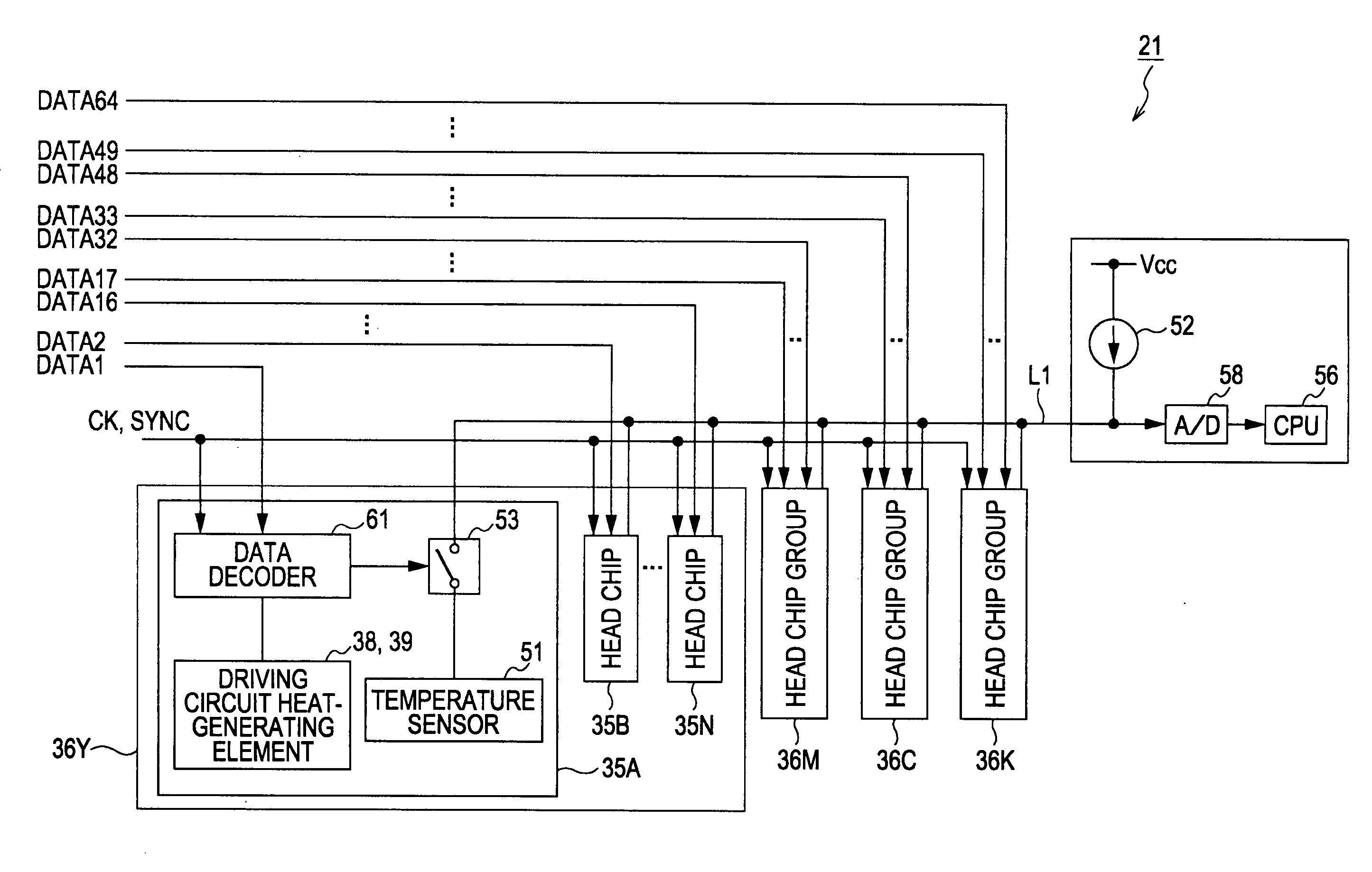
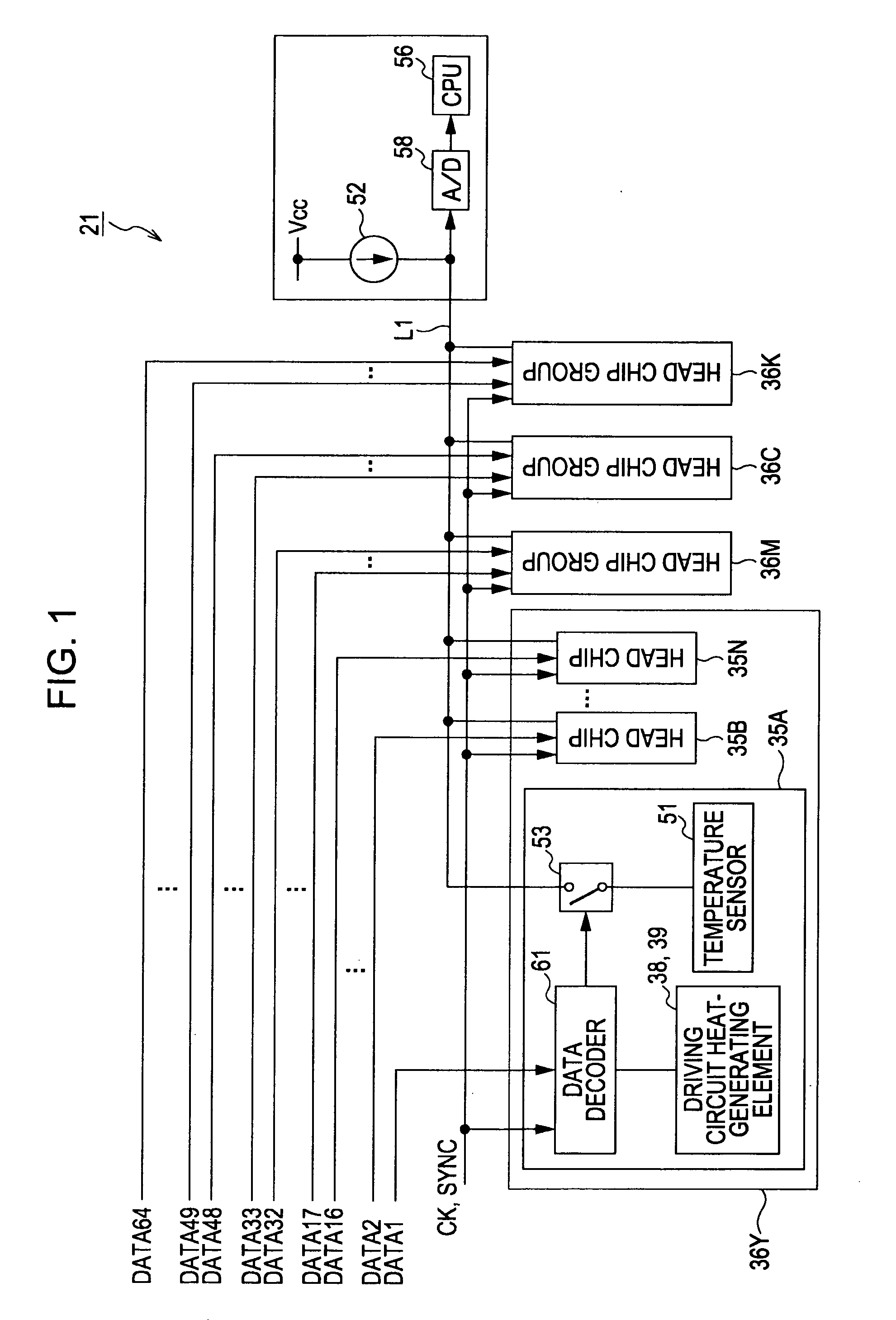
[0015]According to the embodiments of the present invention, the temperature sensors of a plurality of head chips can be sequentially and selectively connected to the electrical current source, and the temperatures of the plurality of head chips can be measured. Therefore, it is possible to reduce the number of wirings of the head chips used to measure temperature. As a result, it is possible to miniaturize the configuration for temperature measurement in comparison with the related art.

Problems solved by technology

The temperature difference causes the amount of ink droplets ejected to vary among the head chips, and print mottling occurs.
Therefore, problems arise in that the area of a motherboard on which the central processing unit 4 and the like are arranged becomes enlarged and the area of the configuration that connects the motherboard to the printer becomes enlarged.

Method used


Image

  • Liquid ejecting apparatus and method of controlling same
  • Liquid ejecting apparatus and method of controlling same
  • Liquid ejecting apparatus and method of controlling same

Examples


first embodiment

(1) Configuration of the Embodiment

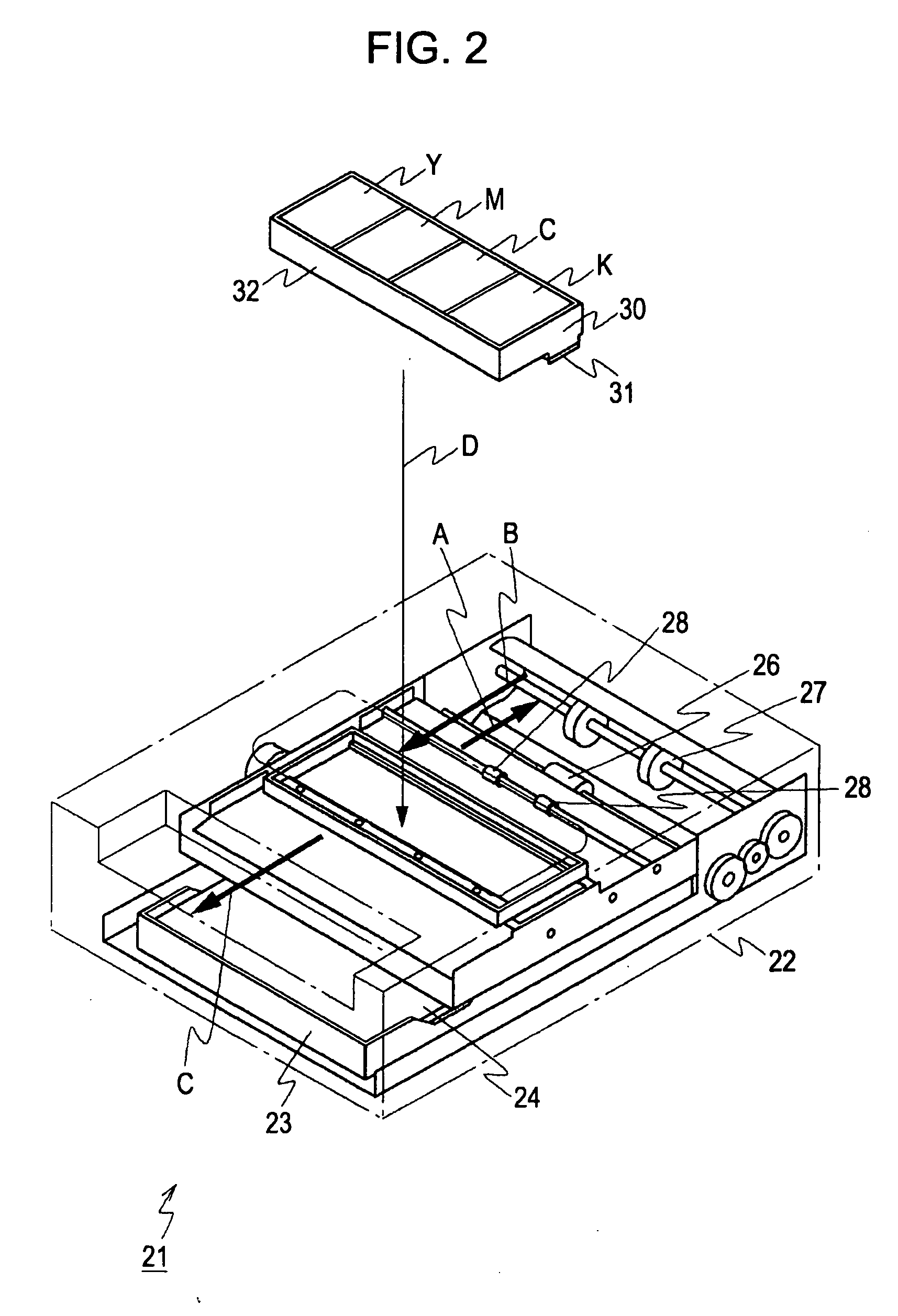
[0024]FIG. 2 is a perspective view showing a printer 21 according to a first embodiment of the present invention. The printer 21 is a line printer. The entirety thereof is formed in such a manner as to be housed in a rectangular housing 22, and a paper tray 23 in which printing paper 24 is housed is installed from the tray entry formed in the front side of the housing 22.

[0025]Here, when the paper tray 23 is installed in the printer 21, a predetermined mechanism causes the printing paper 24 to be pressed against a paper feed roller 26, and as a result of the paper feed roller 26 being rotated, the printing paper 24 is transported toward the side opposite the paper tray 23, as indicated by an arrow mark A. In the printer 21, an inversion roller 27 is disposed on the side at which the paper is fed, and as a result of the inversion roller 27 being rotated, the transport direction of the printing paper 24 is switched toward the front direction, as indi...

second embodiment

[0059]In the above-described embodiment, a case in which control data for switch circuits is transmitted through a transmission line of image print data has been described. The present invention is not limited to this case, and control data for switch circuits may be transmitted through a transmission line differing from that for image print data. In this case, control data may be transmitted in common with a plurality of head chips, thereby preventing an increase in the number of wirings.

[0060]In the above-described embodiment, a case in which outputs of temperature sensors are collected in all the head chips provided in the printer head has been described. The present invention is not limited to this case. The number of head chips to be collected to one output line, for example, in the case they are collected for each head chip group according to ink, can be set variously as necessary.

[0061]In the above-described embodiment, a case in which a temperature sensor is constituted by a...


PUM


Abstract

A liquid ejecting apparatus for ejecting droplets by driving heat generating elements includes an electrical current source configured to output temperature measurement current; a plurality of head chips, each having a heat generating element, a temperature sensor whose resistance value changes with temperature, a switch circuit that connects the temperature sensor to the electrical current source, and a switch-circuit control circuit configured to control the switch circuit; and a heat-generating-element control circuit configured to measure temperatures of the plurality of head chips and controlling the driving of the heat generating elements via an end of the electrical current source on the temperature sensor side. The temperature sensors of the plurality of head chips are sequentially and selectively connected to the electrical current source by the switch circuits of the plurality of head chips, and the temperatures of the plurality of head chips are measured by the heat-generating-element control circuit.

Description

CROSS REFERENCES TO RELATED APPLICATIONS[0001]The present invention contains subject matter related to Japanese Patent Application JP 2007-102304 filed in the Japanese Patent Office on Apr. 10, 2007, the entire contents of which are incorporated herein by reference.BACKGROUND OF THE INVENTION[0002]1. Field of the Invention[0003]The present invention relates to a liquid ejecting apparatus and a method of controlling the liquid ejecting apparatus, and can be applied to, for example, a thermal line printer. In the present invention, an electrical current source for measuring temperature is shared among a plurality of head chips, temperature sensors of each of the head chips are sequentially and selectively connected to the electrical current source, and the temperature of each head chip is measured at the end of the electrical current source side, thereby miniaturizing the configuration for temperature measurement in comparison with the related art.[0004]2. Description of the Related A...

Claims


Application Information

Patent Timeline
Patent Type & Authority Applications(United States)
IPC IPC(8): B41J29/38
CPCB41J2/04563B41J2/0458B41J2/1752B41J2202/19B41J2/1404B41J2/14072B41J2/04541B41J2/045B41J2/05B41J2/14145
Inventor USHINOHAMA, IWAO
Owner SONY CORP
Learn More