
Liquid Crystal Display Device

a liquid crystal display and liquid crystal technology, applied in non-linear optics, instruments, optics, etc., can solve the problems of difficult enhancement of both reflectance and transmittance functions, easy white dropout, and light leakage phenomenon, and achieve the effect of suppressing linear alignment defects and stable display

Inactive Publication Date: 2008-10-16
KYOCERA CORP
View PDF9 Cites 0 Cited by
  • Summary
  • Abstract
  • Description
  • Claims
  • Application Information

AI Technical Summary

Benefits of technology

This configuration achieves stable and uniform liquid crystal displays with reduced white and black dropouts and alignment defects, maintaining high visual recognition without display irregularities across the entire display region.

Problems solved by technology

When such a semi-transmissive film serving as a half mirror is used, it is difficult to enhance both functions of reflectance and transmittance.
For this reason, in a semi-transmissive liquid crystal device, for example, when black is displayed in a transmissive mode (a display state where transmitted light is shielded), white dropouts readily occur due to the transparent spacers per se and an alignment defect of the liquid crystal on the periphery of the spacers.
This is because while liquid crystal molecules are in a twisted state in a space between two substrates, those on the periphery of the spacers go into a state where they apparently stand perpendicularly in the space between the two substrates, and the twisted state of the liquid crystal molecules on the periphery of the spacers is thereby disturbed, which gives rise to a light leaking phenomenon in the liquid crystal layer near the spacer surface.
However, because only part of the pixel contributes to a transmissive display in the transmissive mode, the size of the pixel becomes relatively small with respect to the size of the spacers.
However, there arises another problem that an alignment defect of liquid crystal molecules occurs between close spacers.
However, when hydrophilic spacers are mixed at a high density, an alignment defect of liquid crystal molecules between spacers becomes noticeable.
Conversely, when a scattering density of spacers is reduced to control the linear alignment defects, the thickness of the liquid crystal layer becomes less uniform.
The liquid crystal molecules in the liquid crystal layer then become unable to move stably, which results in a problem that liquid crystal display is disturbed.

Method used


Image

  • Liquid Crystal Display Device
  • Liquid Crystal Display Device
  • Liquid Crystal Display Device

Examples


example 1

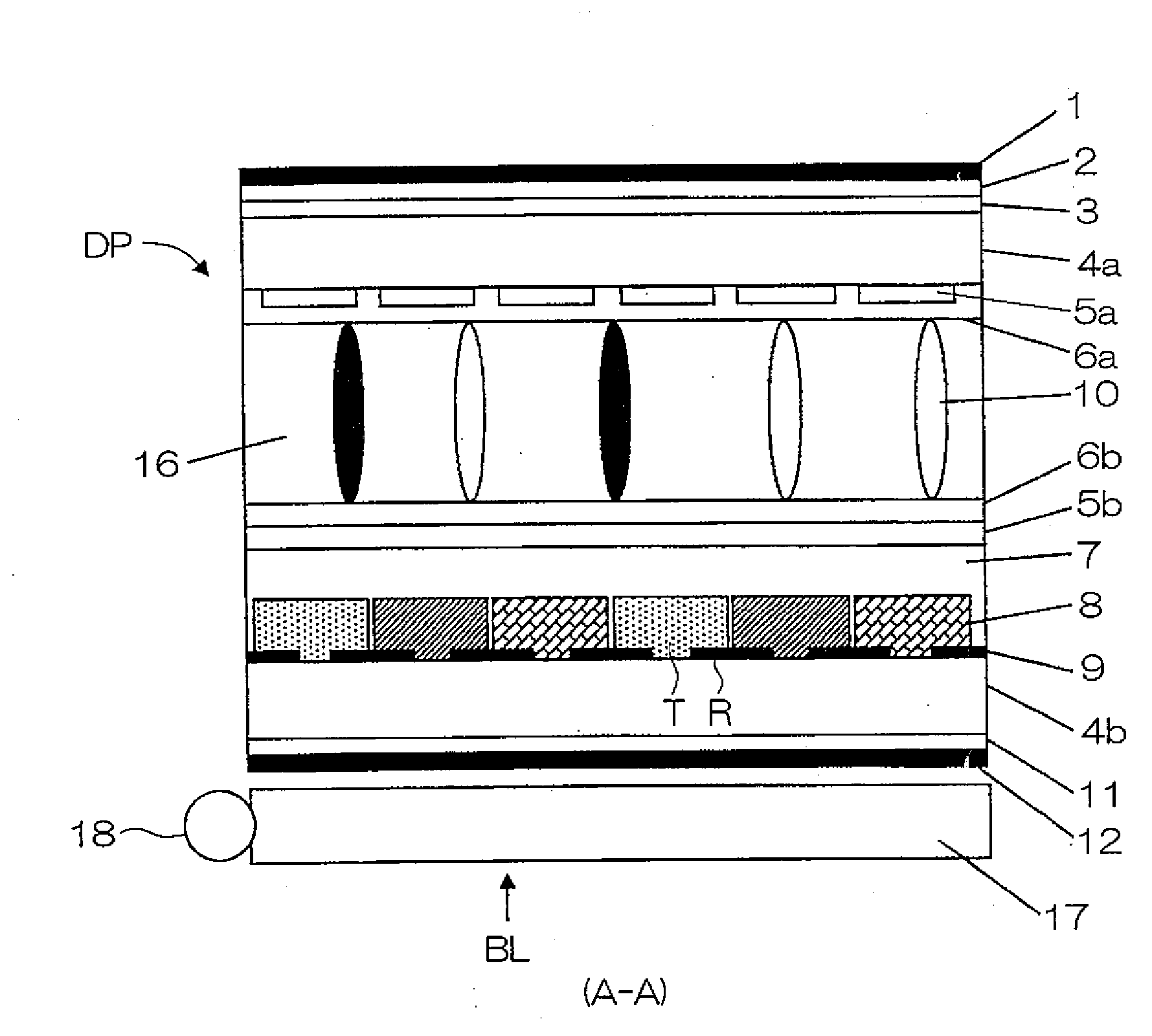
[0094]A semi-transmissive liquid crystal display device having a light reflective region and a light transmissive region in one pixel and provided with transparent spacers at a density of 200 pieces / mm2 was manufactured. Also, a semi-transmissive liquid crystal display device provided with black spacers at a density of 200 pieces / mm2 was manufactured.

[0095]In addition, a semi-transmissive liquid crystal display device provided with semi-transparent spacers at a density of 200 pieces / mm2 was manufactured.

[0096]More specifically, the radius r was set, for example, to 3 μm for each spacer.

[0097]TABLE 1 and TABLE 2 show evaluation results of roughness caused by white dropouts in the black display and roughness caused by black spots in the white display for the value of πr2 / S when NA−NB=1 was given in Equation (1) above.

TABLE 1πr2 / S0.00100.00170.00230.00340.00470.00550.00670.0079TRANSPARENTROUGHNESS IN WHITE DISPLAY◯◯◯◯◯◯◯◯SPACERSROUGHNESS IN BLACK DISPLAY◯◯◯◯◯◯◯◯BLACKROUGHNESS IN WHITE ...

example 2

[0136]Visual recognition and an alignment defect of liquid crystal caused by pressing were checked in a liquid crystal display device using the spacers shown in FIG. 4.

[0137]The black base material particle 20a and a transparent base material particle as a comparative example were prepared as base material particles of the spacers. Further, for the base material particles of each type, those with and without the hydrophilic group film 20b were prepared.

[0138]Further, those with and without the alkyl group film 20c were prepared. Furthermore, for those having the alkyl group film 20c, the thickness (maximum number of carbons) of the alkyl groups was varied in various manners.

[0139]TABLE 6 shows the result when roughness caused by white dropouts in the black display, roughness caused by black spots in the white display, and an alignment defect of liquid crystal caused by pressing were checked in the liquid crystal device using the spacers.

TABLE 6SPACER BASE MATERIALTRANSPARENTBLACKMAX...

example 3

[0177]TABLE 9 shows the result when the spacer density of the hydrophobic spacers 10b, an alignment defect between spacers, leakage of light from the periphery of spacers, uniformity of the panel GAP (thickness of the liquid crystal layer) were checked.

TABLE 9HYDROPHOBIC TREATMENT SPACERDENSITY (PIECES / mm2)20406080100120140160180200ALIGNMENT DEFECT BETWEEN SPACERS⊚⊚⊚⊚⊚⊚⊚⊚⊚⊚LEAKAGE OF LIGHT FROM PERIPHERY OF SPACER⊚⊚⊚⊚⊚◯◯◯ΔXPANEL GAP UNIFORMITYXXXΔΔΔΔ◯◯⊚

[0178]An alignment defect between the hydrophobic spacers 10b is satisfactory when the hydrophobic spacer density is in a range from 20 to 200 pieces / mm2. This is because no alignment restraining force on liquid crystal molecules is exerted on the spacer surface, and no alignment defect occurs between the spacers where spacers are close to each other.

[0179]Leakage of light from the periphery of spacers is satisfactory when the hydrophobic spacer density is in a range from 20 to 100 pieces / mm2; however, it deteriorates as the density o...


PUM

PropertyMeasurementUnit
widthaaaaaaaaaa
widthaaaaaaaaaa
dimensionaaaaaaaaaa

Abstract

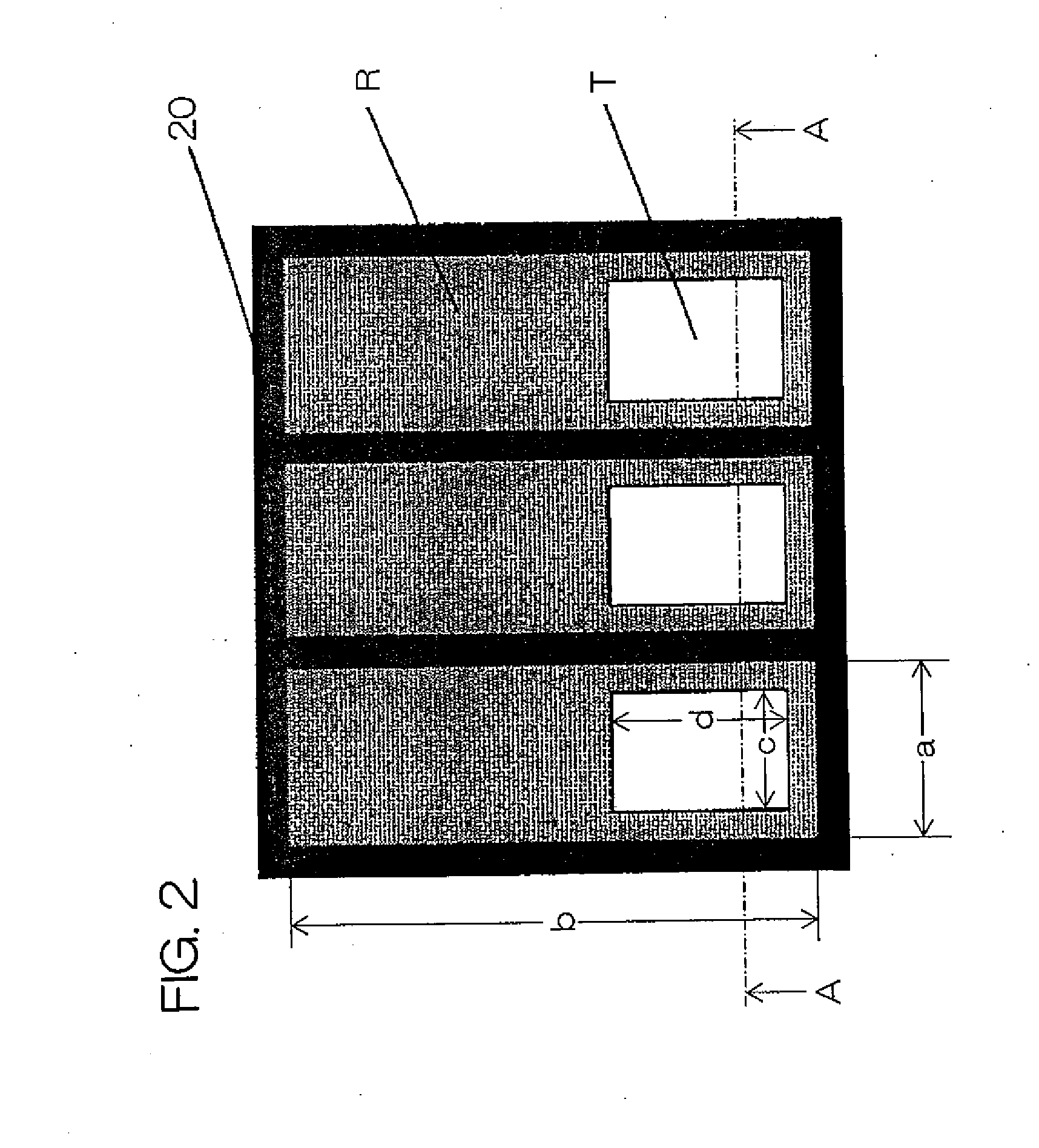
In a semi-transmissive liquid crystal display device provided with a liquid crystal panel DP and a backlight BL, black spacers and transparent spacers are mixed and provided in a space between two opposing transparent substrates 4a and 4b, and let r be a radius of the spacers and S be a dimension of a light transmissive region T in a single pixel, then a value of πr2 / S is set in a range from 0.001 to 0.01. A stable display is thus enabled by eliminating display irregularities.

Description

BACKGROUND OF THE INVENTION[0001]1. Field of the Invention[0002]The present invention relates to a semi-transmissive liquid crystal display device having a light reflective region and a light transmissive region in a single pixel region, and more particularly, to the structure of a spacer that defines an interval between a pair of top and bottom substrates.[0003]2. Description of Related Art[0004]In recent years, a liquid crystal display device has been used extensively as a large-scale, high-definition monitor besides a small- or medium-scale personal digital assistant and a notebook computer.[0005]A display mode of the liquid crystal display device includes a reflective mode in which display is performed using external light that comes incident on the display surface, a transmissive mode in which a backlight is used and display is performed by allowing light from the backlight to pass through the display surface, and a semi-transmissive mode furnished with the functions of both mo...

Claims


Application Information

Patent Timeline
Patent Type & Authority Applications(United States)
IPC IPC(8): G02F1/1339
CPCG02F1/133555G02F1/13392G02F1/1339
Inventor NAGATA, YASUNARI
Owner KYOCERA CORP
Learn More