Light-emitting device with power supply structure

Inactive Publication Date: 2008-10-16
NEC LIGHTING
View PDF4 Cites 12 Cited by
  • Summary
  • Abstract
  • Description
  • Claims
  • Application Information

AI Technical Summary

Benefits of technology

[0012]The present invention aims to provide a light-emitting device which can solve the above-mentioned problems. An example of t

Problems solved by technology

In consequence, in the case of inserting a harness into a power supply terminal which is constructed of a part of th

Method used


Image

  • Light-emitting device with power supply structure
  • Light-emitting device with power supply structure
  • Light-emitting device with power supply structure

Examples


Embodiment Construction

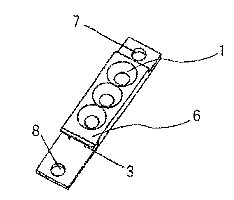
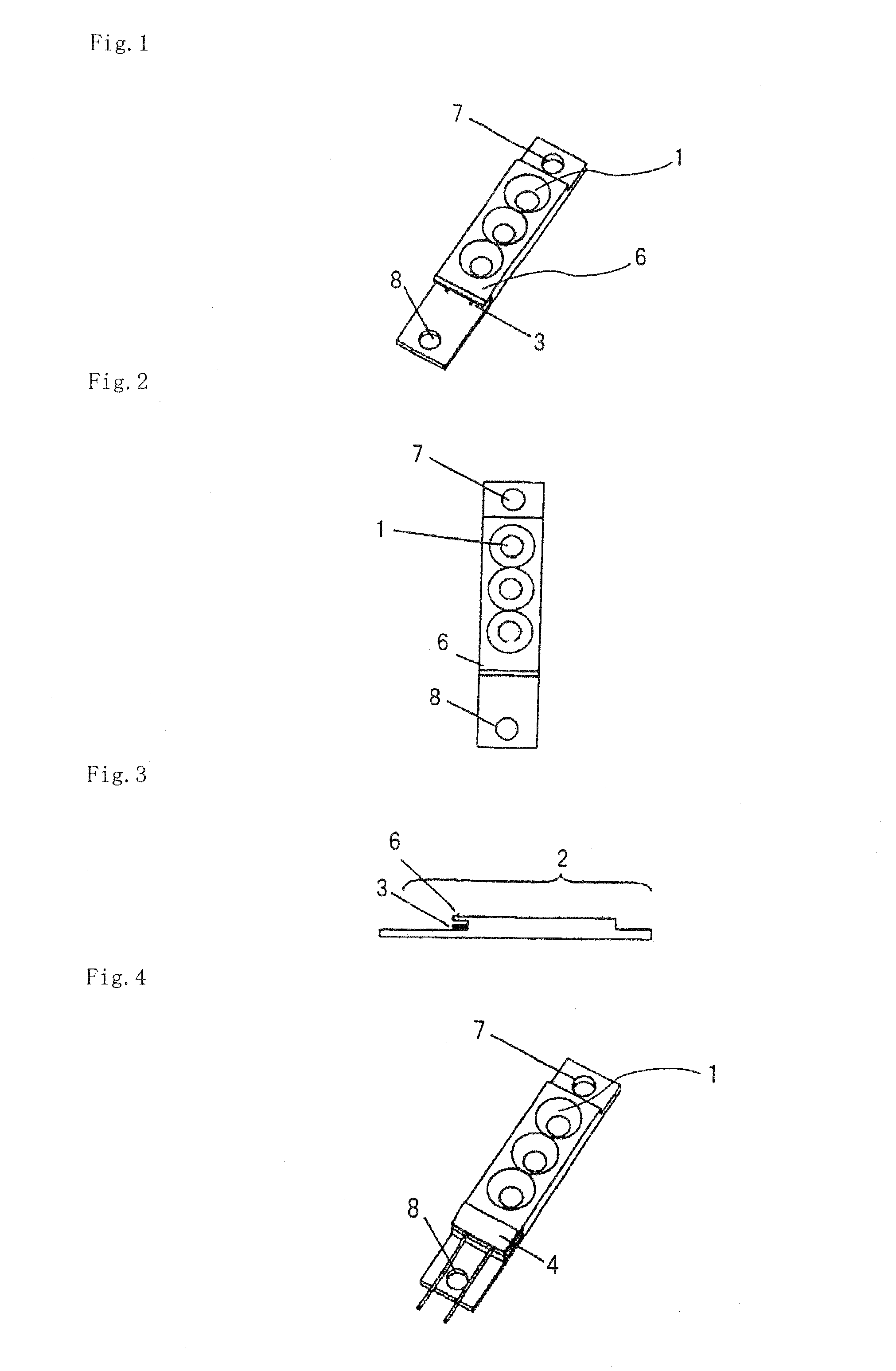
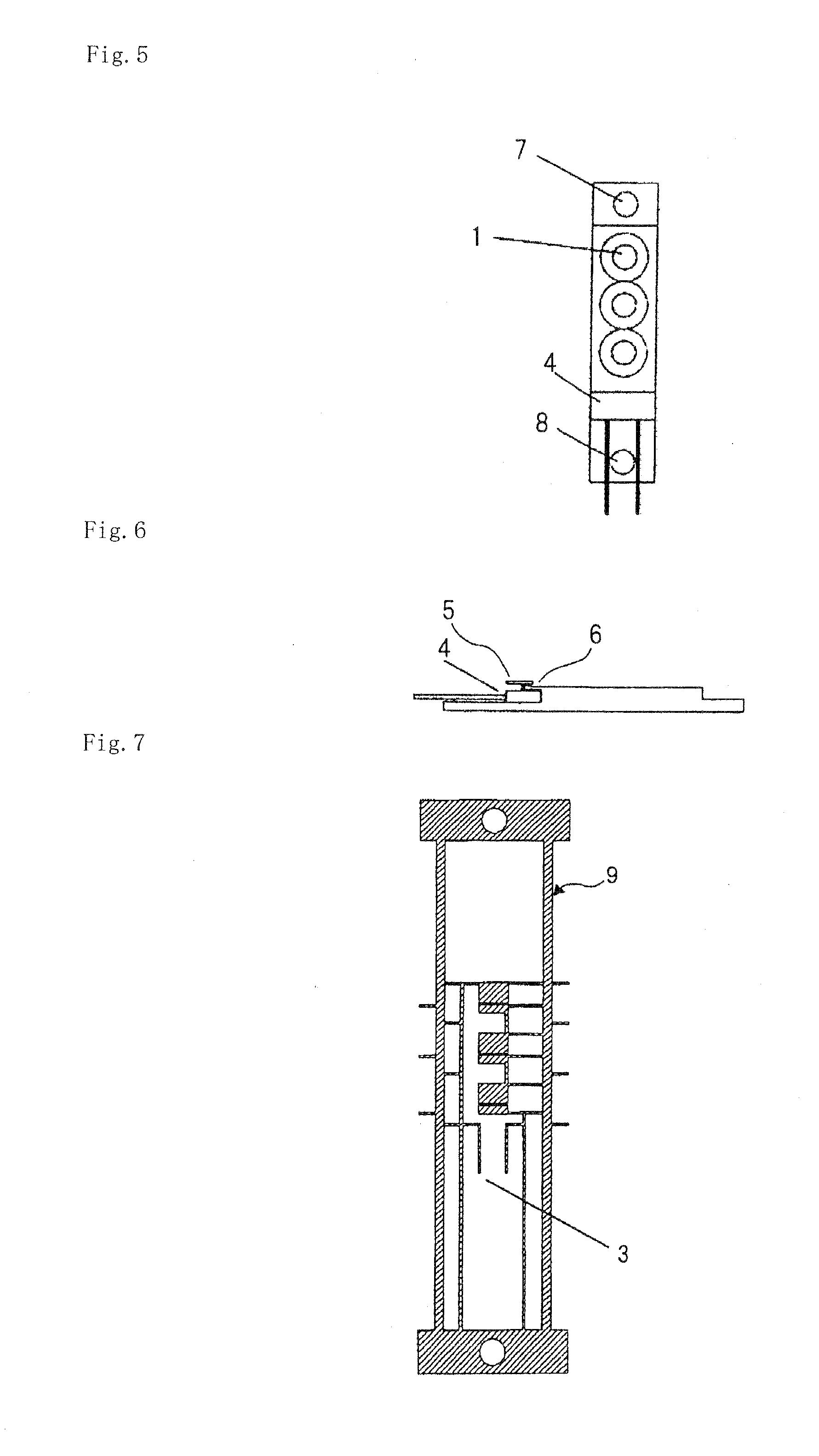
[0026]A light-emitting device of this exemplary embodiment has lead frame 9 and resin mold part 2, as illustrated in FIGS. 1 to 7. A plurality of light emitting elements, such as an LED, is bonded and mounted in lead frame 9. Electric power is supplied to respective light emitting elements through lead frame 9. Resin mold part 2 not only forms a plurality of light emitting parts 1 from which the light emitting elements are exposed, but also covers lead frame 9.

[0027]A part of lead frame 9 is exposed from one side surface of an upper portion of resin mold part 2. This portion becomes terminals 3 for supplying power in which a harness is inserted.

[0028]These terminals 3 are formed by bending a part of lead frame 9 to increase the strength of terminals 3, and then by exposing the part out of resin mold part 2.

[0029]In particular, as to locations used as terminals 3, after bending a lead part, each end portion 9a is made to stand orthogonally to the lead part as illustrated in FIG. 8. I...


PUM


Abstract

A light-emitting device of the present invention comprises a plurality of light emitting elements, a lead frame on which the light emitting elements are mounted and which supplies electric power to the light emitting elements, and a mold part which not only forms a plurality of light emitting parts from which the light emitting elements are exposed, but also covers the lead frame. In addition, a part of the lead frame is exposed from the mold part as a terminal for supplying power which a harness is connected, and, a portion which corresponds to the terminal for supplying power in the lead frame becomes thicker than other portions.

Description

[0001]This application is based upon and claims the benefit of priority from Japanese patent application No. 2007-105789, filed on Mar. 13, 2007, the disclosure of which is incorporated herein in its entirety by reference.BACKGROUND OF THE INVENTION[0002]1. Field of the Invention[0003]The present invention relates to a power supply structure for a light-emitting device.[0004]2. Description of the Related Art[0005]A light-emitting device using a current lead frame package is designed on the assumption that power is supplied by soldering light-emitting devices to a printed wiring board. In particular, in the case of an illumination application for which large amount of light was necessary, power was supplied to a light-emitting device by the following method.[0006]That is, a plurality of light-emitting devices are mounted on a printed wiring board, and this printed wiring board is attached to lighting equipment to be connected mechanically and electrically. A method of supplying power...

Claims


Application Information

Patent Timeline
IPC IPC(8): F21V21/00H01L33/62
CPCB41J2/45F21K9/00F21V19/001H01L25/0753H01L33/62F21K9/30F21Y2103/003F21V23/06H01L2924/0002H01L2924/00F21K9/20F21Y2103/10F21Y2115/10
Inventor OKIMURA, KATSUYUKI
Owner NEC LIGHTING
Why Eureka
Try Eureka