Upper internals arrangement for a pressurized water reactor

a pressurized water reactor and internal arrangement technology, applied in nuclear reactors, nuclear elements, greenhouse gas reduction, etc., can solve problems such as significant repair problems

Active Publication Date: 2008-10-16
WESTINGHOUSE ELECTRIC CORP
View PDF9 Cites 26 Cited by
  • Summary
  • Abstract
  • Description
  • Claims
  • Application Information

AI Technical Summary

Problems solved by technology

In a few instances in the past leakage occurred at the penetrations at the bottom of the vessel which presented significant repair problems.

Method used


Image

  • Upper internals arrangement for a pressurized water reactor
  • Upper internals arrangement for a pressurized water reactor
  • Upper internals arrangement for a pressurized water reactor

Examples


Embodiment Construction

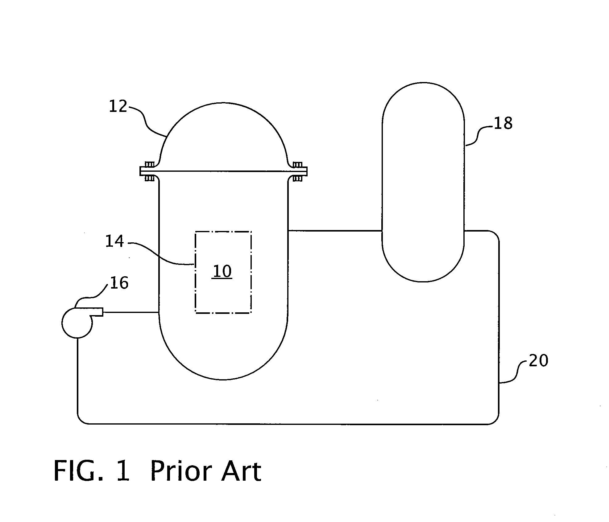
[0016]Referring now to the drawings, FIG. 1 shows a simplified nuclear reactor primary system, including a generally cylindrical reactor pressure vessel 10 having a closure head 12 enclosing a nuclear core 14. A liquid reactor coolant, such as water, is pumped into the vessel 10 by pump 16 through the core 34 where heat energy is absorbed and is discharged to a heat exchanger 18, typically referred to as a steam generator, in which heat is transferred to a utilization circuit (not shown) such as a steam driven turbine-generator. The reactor coolant is then returned to the pump 16, completing the primary loop. Typically, a plurality of the above-described loops are connected to a single reactor vessel 10 by reactor coolant piping 20.

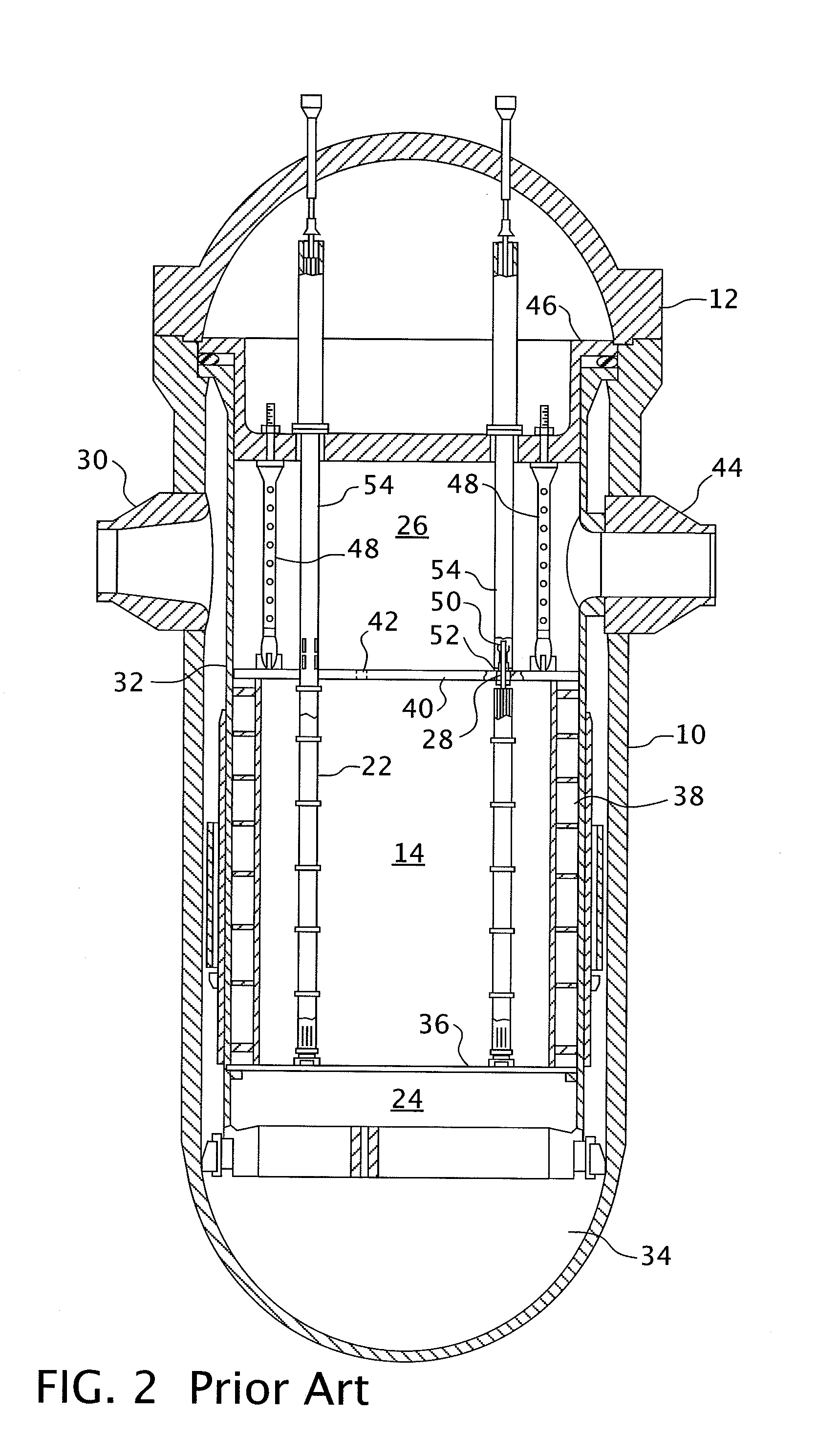
[0017]A conventional reactor design is shown in more detail in FIG. 2. As previously mentioned, though not shown in FIG. 2, in a conventional pressurized water reactor design, the movable in-core neutron detectors enter the core from the bottom of the rea...


PUM


Abstract

In a pressurized water reactor with ail of the in-core instrumentation gaining access to the core through the reactor head, each fuel assembly in which the instrumentation is introduced is aligned with an upper internals instrumentation guide-way. In the elevations above the upper internals upper support assembly, the instrumentation is protected and aligned by upper mounted instrumentation columns that are part of the instrumentation guide-way and extend from the upper support assembly towards the reactor head in hue with a corresponding head penetration. The upper mounted instrumentation columns are supported laterally at one end by an upper guide tube and at the other end by the upper support plate.

Description

BACKGROUND OF THE INVENTION[0001]1. Field of the Invention[0002]This invention relates to water-cooled nuclear reactors, and more particularly to pressurized water reactors having in-core instrumentation that enter the reactor vessel through penetrations from the top of the reactor vessel and are used to monitor the neutron activities and coolant temperature within the core fuel assemblies.[0003]2. Description of the Prior Art[0004]Many water-cooled nuclear reactors utilize a core of vertically-positioned fuel assemblies within a reactor vessel. To monitor the neutron activities and coolant temperature within the core fuel assemblies, movable in-core instrumentation, such as movable neutron detectors, conventionally enter the core from penetrations in the bottom of the vessel. In a few instances in the past leakage occurred at the penetrations at the bottom of the vessel which presented significant repair problems. Accordingly, it would he desirable to have all the in-core instrumen...

Claims


Application Information

Patent Timeline
Patent Type & Authority Applications(United States)
IPC IPC(8): G21C7/08
CPCG21C13/02G21Y2002/201G21Y2002/301G21Y2002/402G21Y2004/30Y02E30/40Y02E30/30
Inventor SINGLETON, NORMAN R.ALTMAN, DAVID A.YU, CHINGREX, JAMES A.FORSYTH, DAVID R.
Owner WESTINGHOUSE ELECTRIC CORP
Why Eureka
Try Eureka