Spinal distraction system

a spinal distraction and system technology, applied in the field of spinal distraction systems, can solve the problems of pain and debilitating back pain, many of the available spinal distraction systems are very complicated to use, improper use of spinal distraction systems can have serious and permanent medical consequences, etc., and achieve the effect of accurate and uncomplicated

Inactive Publication Date: 2008-10-16
HOSPITAL FOR SPECIAL SURGERY
View PDF37 Cites 40 Cited by
  • Summary
  • Abstract
  • Description
  • Claims
  • Application Information

AI Technical Summary

Benefits of technology

[0018]First and second nuts preferably are threadedly engaged on the second rod. The first nut is disposed between the fixed and movable legs. The second nut is disposed between the second leg and the connection between the ends of the rods. The nuts can be rotated on the second rod to fix the position of the movable leg relative to the fixed leg and / or to limit the range of movement of the fixed leg relative to the movable leg. For example, the nuts can be disposed so that movement of the movable leg in one direction is prevented but limited movement of the movable leg in the opposed direction is permitted. Washers may be disposed on the second rod between the movable leg and the nuts.

Problems solved by technology

Injury, disease and various other conditions can lead to very painful and debilitating back problems.
Many of the available spinal distraction systems are very complicated to use.
Improper use of a spinal distractor can have serious and permanent medical consequences.
Furthermore, many prior art surgical distraction devices are large and adversely limit access of the surgeon to the desired intervertebral space.

Method used


Image

  • Spinal distraction system
  • Spinal distraction system
  • Spinal distraction system

Examples


Embodiment Construction

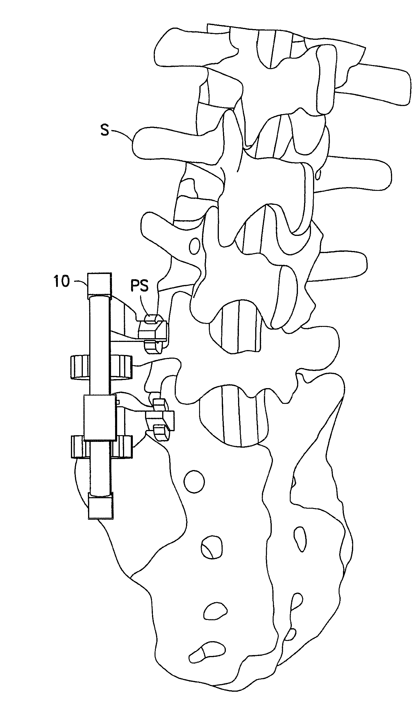
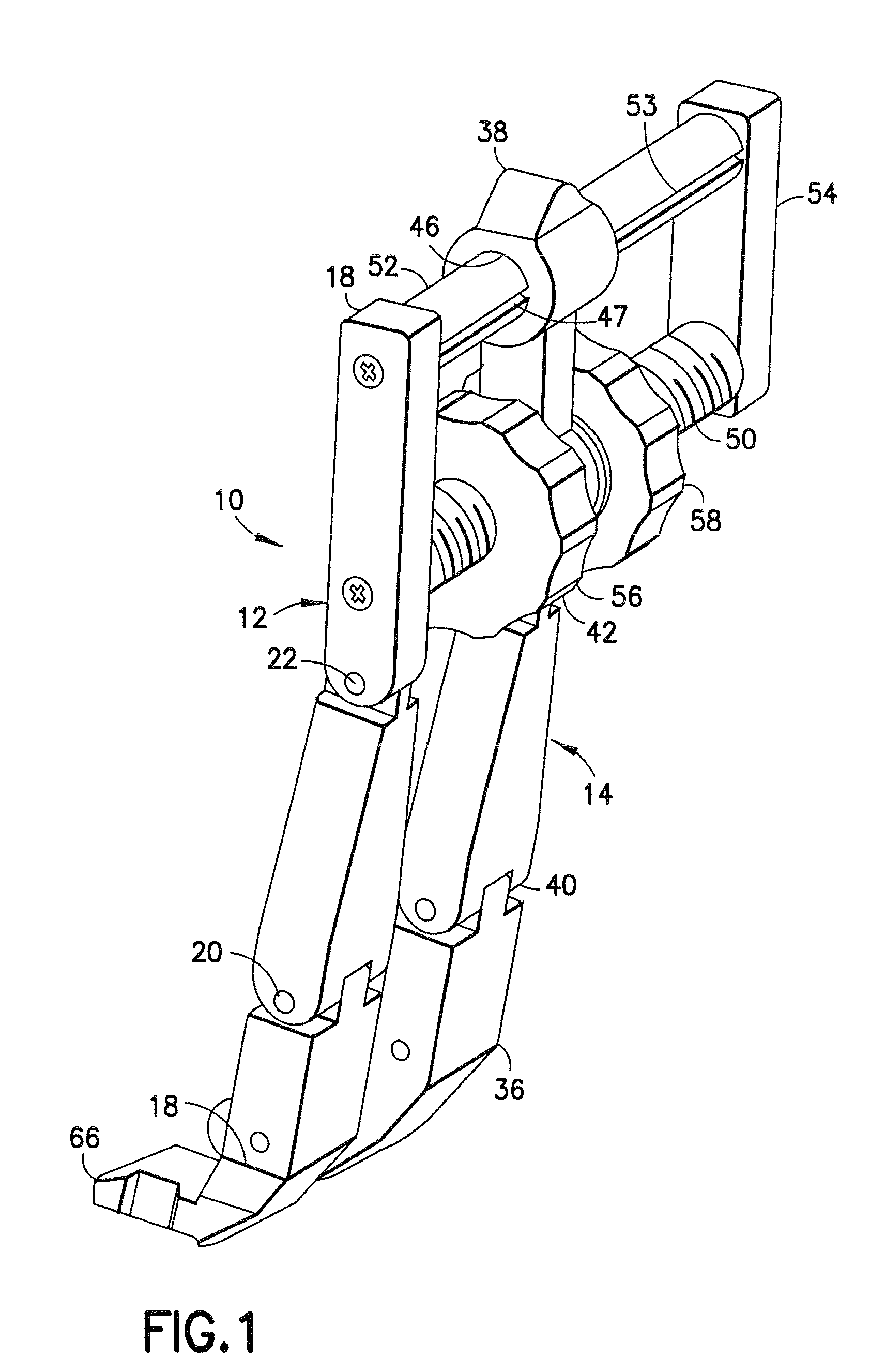
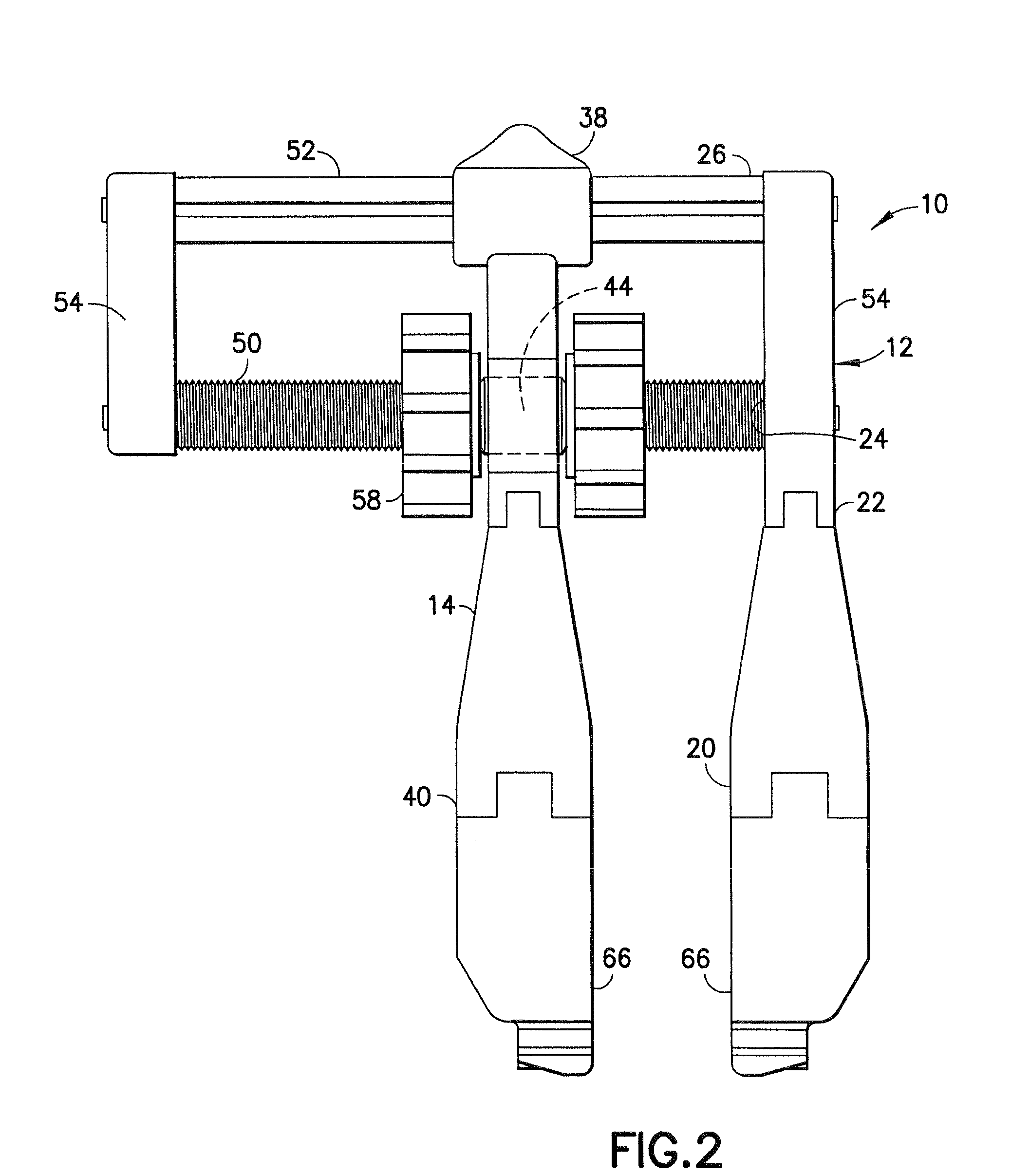
[0042]A spinal distraction apparatus in accordance with one embodiment of the subject invention is identified generally by the numeral 10 in FIGS. 1-6. The spinal distraction apparatus 10 includes a fixed leg 12 and a movable leg 14 that are aligned substantially parallel to one another. The fixed leg 12 has opposite front and rear ends 16 and 18. A front hinge 20 is disposed between the front and rear ends 16 and 18 of the fixed leg 12 and a rear hinge 22 is disposed between the rear end 18 of the fixed leg 12 and the front hinge 22. The front and rear hinges 20 and 22 are configured to rotate about parallel axes that extend in left-to-right directions in FIG. 2. A front rod socket 24 is formed in one side of the fixed leg 12 between the rear end 18 and the rear hinge 22. A rear rod socket 26 is formed in the fixed leg 12 substantially adjacent the rear end 18 and on the same side of the fixed leg 12 as the front rod socket 24. An attachment socket 28 is formed in the front end 16 ...


PUM


Abstract

A spinal distraction apparatus includes substantially parallel fixed and movable legs, each of which has opposite front and rear ends. A rear rod projects rigidly from the rear end of the fixed leg and passes slidably through the rear end of the movable leg. A front rod extends rigidly from the fixed leg and is parallel to the rear rod. The front rod is formed with an array of external threads and nuts are threadedly engaged on the external threads for engaging opposite sides of the movable leg at locations adjacent the front rod. Thus, the position of the movable leg relative to the fixed leg can be controlled by adjusting the positions of the nuts. Front ends of the fixed and movable legs have attachments mounted thereto for engaging pedicle screws or other structures used in spinal distraction surgery.

Description

[0001]This application claims priority on U.S. Provisional Application No. 60 / 922,725 filed on Apr. 10, 2007.BACKGROUND OF THE INVENTION[0002]1. Field of the Invention[0003]The invention relates to an apparatus for distracting portions of the spine during various types of spinal surgery.[0004]2. Description of the Related Art[0005]Injury, disease and various other conditions can lead to very painful and debilitating back problems. These problems often require surgical intervention so that the patient can resume a pain-free active life. Some spinal surgery fuses two or more vertebrae in a fixed relationship to one another. These surgical procedures can be carried out at different locations along the spine and can approach the spine from different angular orientations. The various types of spinal fusion include posterior lumbar interbody fusion, transforaminal lumbar interbody fusion, anterior lumbar interbody fusion and anterior cervical inter body fusion. Many of these procedures in...

Claims


Application Information

Patent Timeline
Patent Type & Authority Applications(United States)
IPC IPC(8): A61B17/58
CPCA61B17/025A61B17/86A61B2017/00685A61B2017/0256A61B17/7077
Inventor ACCORDINO, JOSEPH
Owner HOSPITAL FOR SPECIAL SURGERY
Why Eureka
Try Eureka