
Bolstered mattress

a mattress and bolster technology, applied in the field of beds, can solve the problems of inconvenient design of hospital beds and injuries to patients, and achieve the effect of inhibiting the formation of pressure sores

Inactive Publication Date: 2008-10-23
KCI LICENSING INC
View PDF31 Cites 16 Cited by
  • Summary
  • Abstract
  • Description
  • Claims
  • Application Information

AI Technical Summary

Benefits of technology

The patent describes a medical bed with a mattress support surface and a mattress designed for use with a medical / surgical bed frame. The mattress has a central portion with an upper surface for supporting a patient's body and a lower surface that interfaces with the frame. The mattress has right and left side bolsters that define recesses of reduced bolster height in relation to the upper surface of the central portion. The mattress cover extends about the central portion and both bolsters, forming a single mattress assembly. The bed also has a side rail and a control panel mounted on the side rail. The foam used for the mattress has a specific shape, density, and indentation load deflection to prevent pressure sores on the patient's skin. The foam density for each bolster is selected to provide a passive reminder to the patient of a lateral edge of the mattress. The technical effects of this invention include improved patient comfort, reduced risk of pressure sores, and improved maneuverability for medical professionals.

Problems solved by technology

The bed frame usually has bilateral side rails positioned on the upper and lower portion of the bed frame that are designed to keep mentally or physically impaired patients from accidentally rolling off of the bed and falling on the floor, possibly resulting in an injury to the patients.
Unfortunately, the design of the hospital bed does not prevent and, in fact, contributes to other injuries to a certain group of patients, for example patients with pre-existing conditions such as altered mental status (organic or acquired), confusion, restlessness, or lack of muscle control.

Method used


Image

  • Bolstered mattress
  • Bolstered mattress
  • Bolstered mattress

Examples


Embodiment Construction

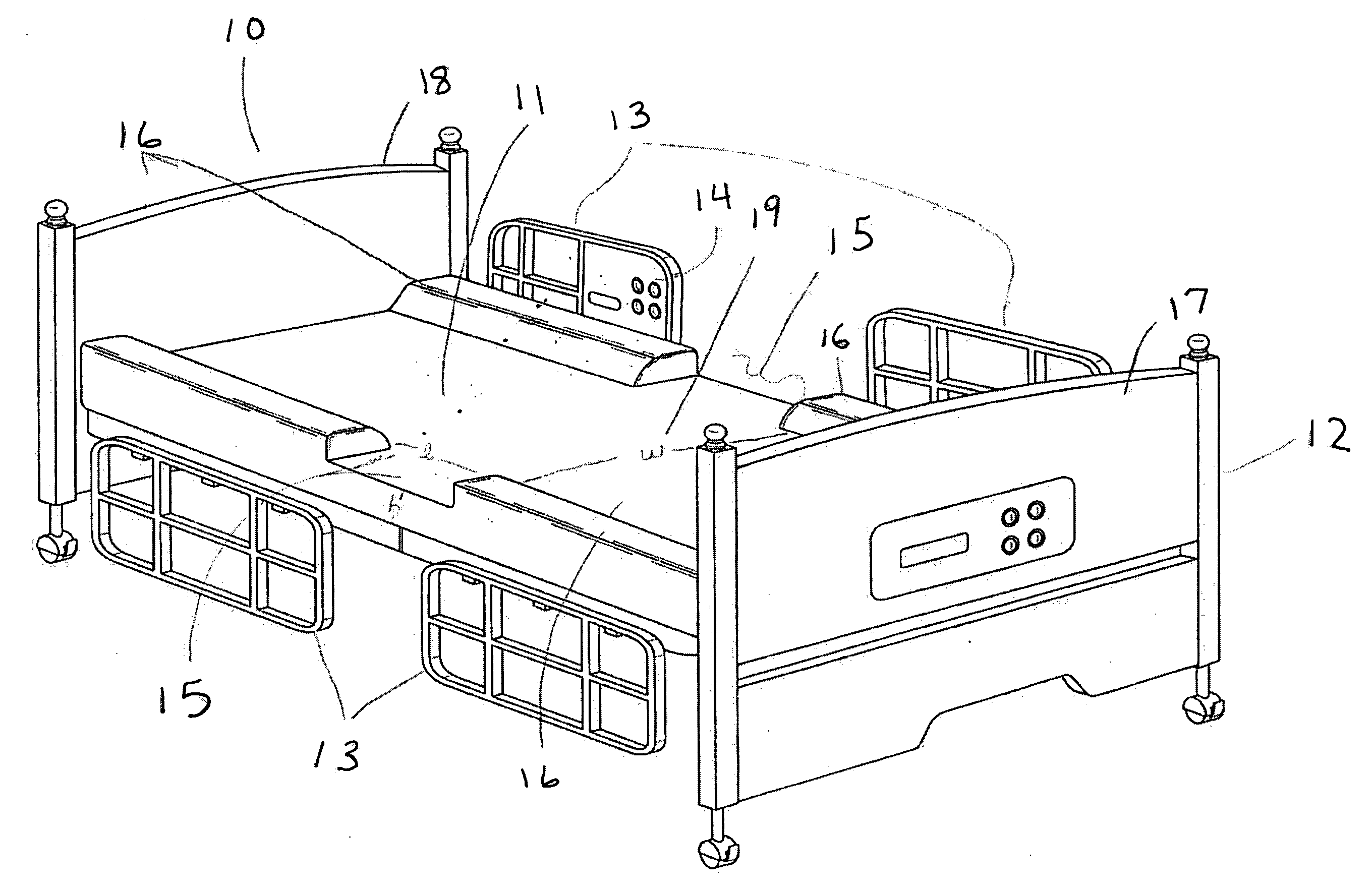
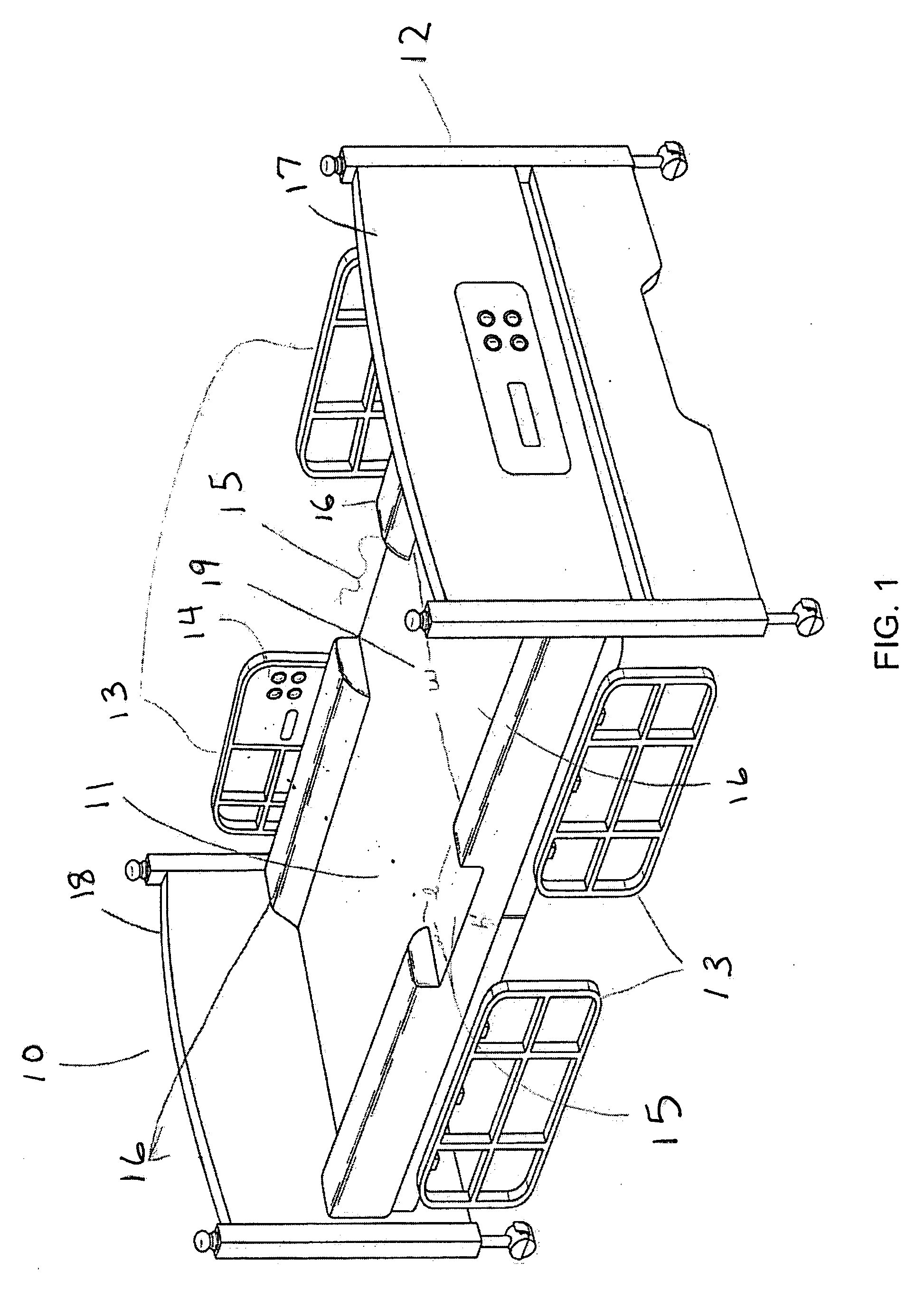
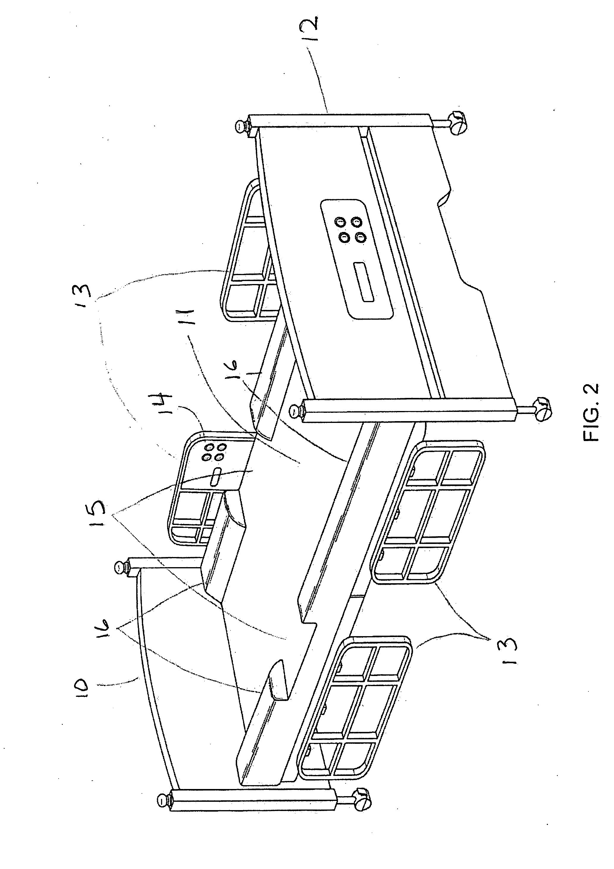
[0016]Referring to FIG. 1-3, a hospital bed 10, which can be used in the medical, surgical, psychiatric, and extended care setting, is shown. Typically, the bed 10 has a frame 12, with one or more side rails 13 (usually four side rails), and a mattress 11. One or more of the side rails 13 can have controls on the side rail for controlling such things as a television, or the bed itself, i.e. adjusting the bed height, or raising or lowering the head or foot of the bed, etc. The side rails 13 can be positioned in at least a raised or lowered position, the respective positions either preventing a patient from falling out of the bed or allowing the patient to enter or exit the bed 10.

[0017]As seen if FIG. 3, the bed 10 has a mattress receiving surface 31 upon which the mattress rests when placed on the bed frame. This surface can be any type of surface that provides support for the mattress 11. Referring to FIG. 1-3, mattress 11 sits on top of mattress receiving surface 31 between a head...


PUM


Abstract

A medical bed having a frame with a mattress support surface. A mattress having a central portion, which has an upper surface adapted to support a patient's body, and a lower surface to interface with the support surface of the frame. The mattress has a right and a left side bolster disposed on opposite sides of the central portion, each bolster extending above the upper surface. Each bolster defines a recess of reduced bolster height in relation to the upper surface of the central portion of the mattress. The mattress has a mattress cover extending about the central portion and both bolsters, such that the mattress and cover together form a single mattress assembly.

Description

TECHNICAL FIELD[0001]This invention relates to beds, such as hospital or medical / surgical beds, and mattresses for such beds.BACKGROUND OF THE INVENTION [0002]Hospital beds or medical / surgical beds are used by patients during a hospital stay, and are also employed for in-home care. A typical hospital bed has a bed frame and a mattress positioned upon the bed frame. The bed frame usually has bilateral side rails positioned on the upper and lower portion of the bed frame that are designed to keep mentally or physically impaired patients from accidentally rolling off of the bed and falling on the floor, possibly resulting in an injury to the patients. The side rails can be positioned in an up position, where they block patients from rolling off the bed, or positioned in a down position that allows patients freedom to enter or exit the mattress arranged upon the bed frame.[0003]Unfortunately, the design of the hospital bed does not prevent and, in fact, contributes to other injuries to ...

Claims


Application Information

Patent Timeline
Patent Type & Authority Applications(United States)
IPC IPC(8): A47C21/08A47C27/00
CPCA47C21/08A47C31/105A61G7/0507
Inventor LARSEN, ERIK N.
Owner KCI LICENSING INC
Learn More