
Motor Actuator and Opening/Closing Device

a technology of motor actuator and opening/closing device, which is applied in the direction of lighting and heating apparatus, heating apparatus, and heating equipment, etc., can solve the problems of complicated structure of the control circuit for changing the rotating direction of the motor, and achieve the effect of reducing the size of the motor actuator, narrowing the operating space of the rack member, and simplifying the control circuit of the motor actuator

Active Publication Date: 2008-10-23
SANKYO SEIKI MFG CO LTD
View PDF7 Cites 19 Cited by
  • Summary
  • Abstract
  • Description
  • Claims
  • Application Information

AI Technical Summary

Benefits of technology

[0006]In view of the problems described above, the present invention may provide a motor actuator in which the rotation of a motor is not required to be reversed even when a driven member is operated in both directions. Further, another object of the present invention is to provide an opening / closing device in which the rotation of a motor is not required to be reversed when an opening / closing member is performed in an opening and a closing operations.
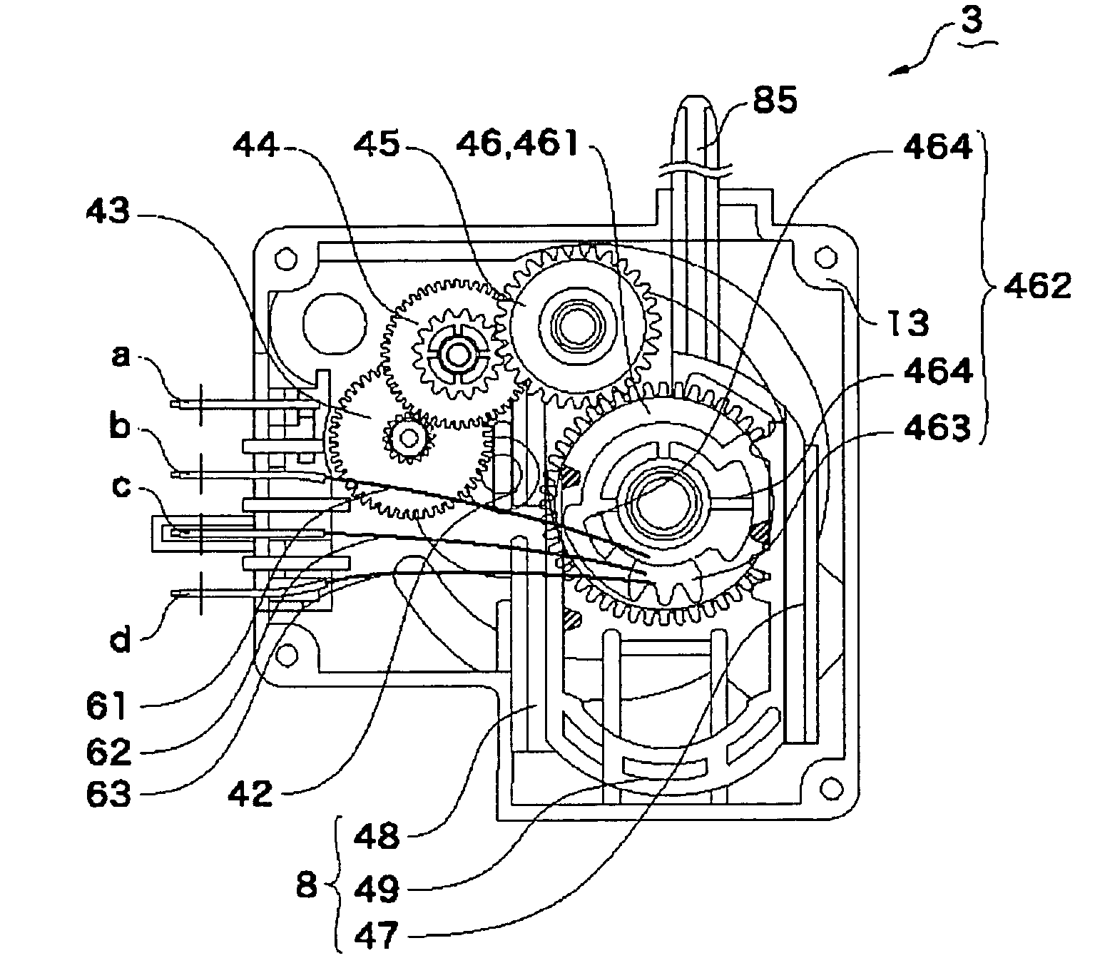
[0008]In a motor actuator, when the motor in the driving force transmission mechanism rotates in one direction and the tooth-missing gear part engages with the first rack part of the rack member, the rack member may be moved in one direction to operate the driven member in a predetermined direction, and when the tooth-missing gear part engages with the second rack part of the rack member, the rack member is moved in the other direction to operate the driven member in an opposite direction. As described above, even when the driven member is operated in both directions, the gear is required to be turned in only one direction and the rotation of the motor is not required to be reversed and thus the structure of a control circuit of the motor actuator can be simplified.
[0009]Thus, it is preferable that the tooth-missing gear part is in a non-engagement state with the second rack part when the tooth-missing gear part engages with the first rack part, and the tooth-missing gear part is in a non-engagement state with the first rack part when the tooth-missing gear part engages with the second rack part. According to the structure as described above, when the tooth-missing gear part engages with the first rack part to move the rack member in one direction, since the tooth-missing gear part does not engage with the second rack part, the rack member does not receive unnecessary force between the second rack part and the tooth-missing gear part. On the other hand, when the tooth-missing gear part engages with the second rack part to move the rack member in the other direction, since the tooth-missing gear part does not engage with the first rack part, the rack member does not receive unnecessary force between the first rack part and the tooth-missing gear part.
[0010]Thus, it is preferable that the first rack part and the second rack part are extended in parallel to each other. According to the structure as described above, the rack member can be reciprocated only in the direction where the first rack part and the second rack part are extended and thus operating space of the rack member can be narrowed. Accordingly, the size of the motor actuator can be reduced.
[0011]Thus, it is also preferable that the rack member is provided with a pair of inner side portions between which the gear is disposed and which are extended in parallel to each other, and the first rack part is formed in one of a pair of the inner side portions and the second rack part is formed in the other of a pair of the inner side portions. According to the structure as described above, the rack member can be driven in both directions with only one gear and thus the number of components and space can be reduced. Further, since the first rack part and the second rack part are extended in parallel to each other, the rack member can be reciprocated only in the direction in which the first rack part and the second rack part are extended. Therefore, since operating space of the rack member may be narrowed, the size of the motor actuator can be reduced.
[0012]Thus, it may be structured that the driving force transmission mechanism includes, as the gear, a first gear on one side of both side positions of the rack member and a second gear on the other side of the both side positions, and the rack member is provided with a pair of outer side portions which respectively face on opposite sides and are extended in parallel to each other, and the first rack part is formed in one of a pair of the outer side portions and the second rack part is formed in the other of a pair of the outer side portions. According to the structure as described above, since the rack member can be reciprocated only in the direction in which the first rack part and the second rack part are extended, operating space of the rack member may be narrowed. Therefore, the size of the motor actuator can be reduced.

Problems solved by technology

Hei 6-109354, opening / closing of the baffle is performed by means of that the motor is forwardly and reversely rotated to move the engaging shaft up and down and thus the structure of a control circuit for changing the rotating direction of the motor becomes complicated.

Method used


Image

  • Motor Actuator and Opening/Closing Device
  • Motor Actuator and Opening/Closing Device
  • Motor Actuator and Opening/Closing Device

Examples


Embodiment Construction

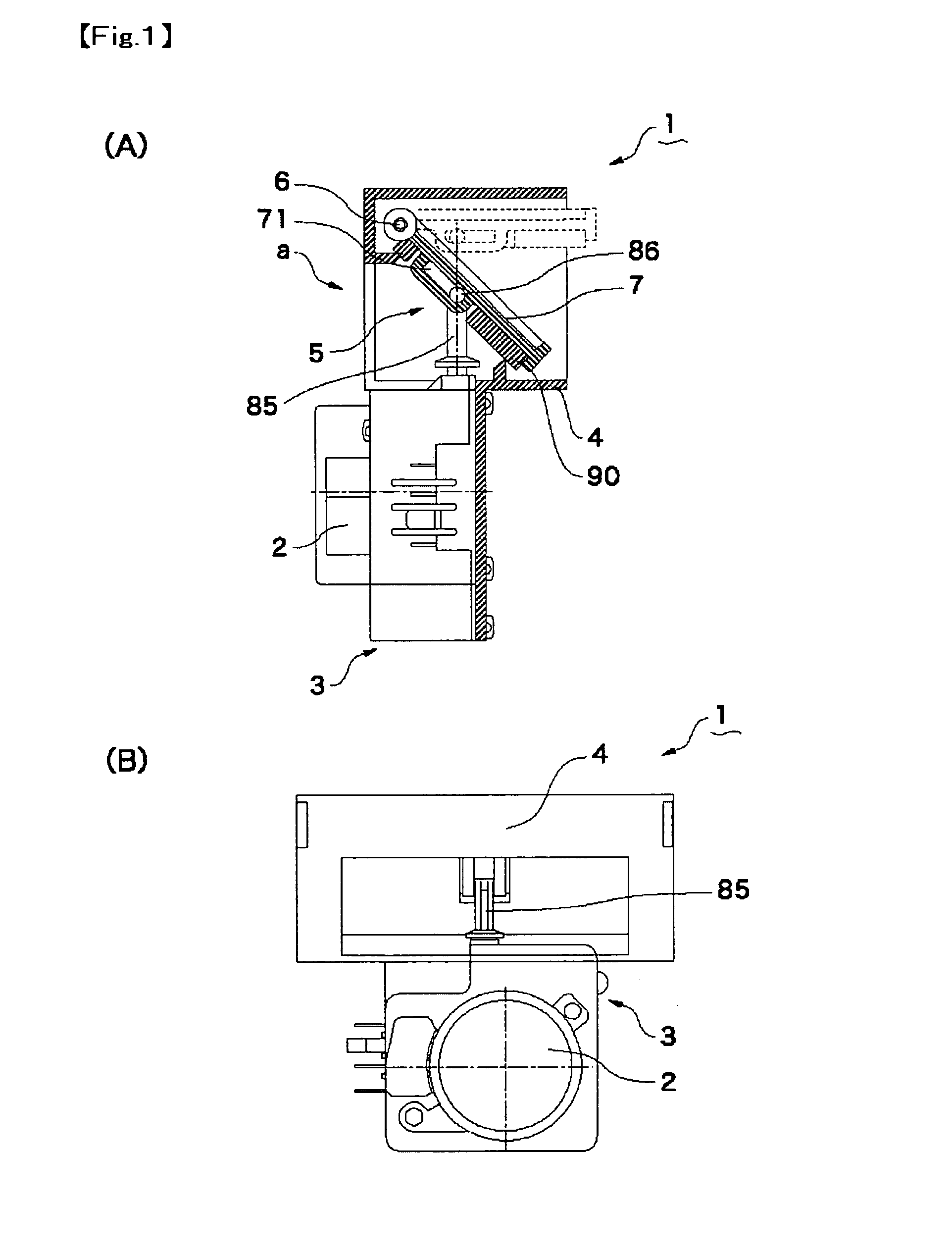
[0034]As a motor actuator to which the present invention is applied, an opening / closing device for causing a baffle (driven member) used in a refrigerator to perform opening or closing operation will be described below with reference to the accompanying drawings.

[0035](Entire Structure of Opening / Closing Device)

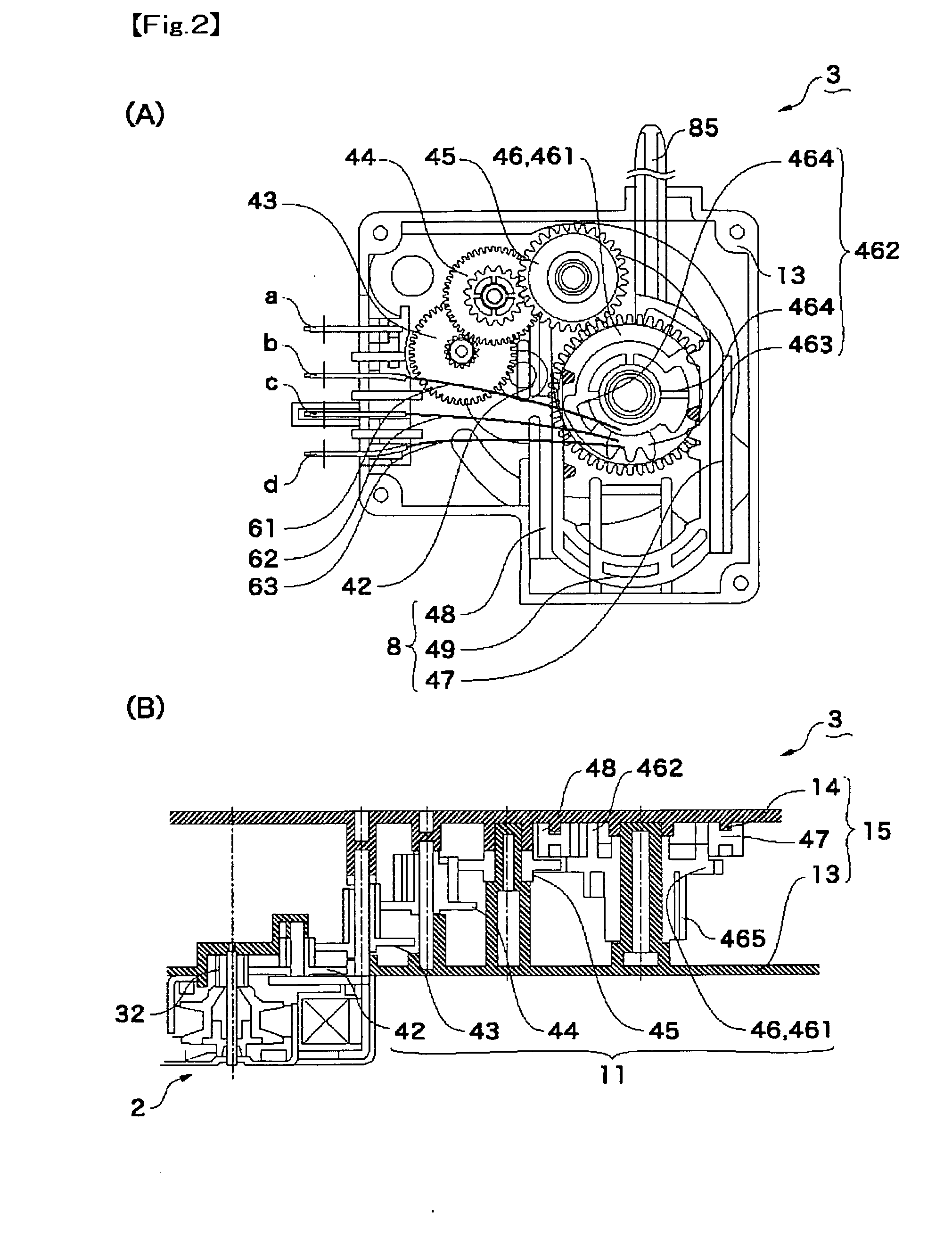
[0036]FIG. 1(A) is a partly sectional explanatory view showing an opening / closing device to which the present invention is applied and FIG. 1(B) is a rear view showing the opening / closing device which is viewed from the direction of “a” in FIG. 1(A). FIG. 2(A) is a plan view showing a geared motor which is used in the opening / closing device shown in FIG. 1 and FIG. 2(B) is a developed view showing a gear train of the geared motor. FIGS. 3(A), 3(B), 3(C), 3(D) and 3(E) are explanatory views for explaining the structure and operation of the opening / closing device shown in FIG. 1. The left side views show positional relationships between a cam member and contact pieces which are...


PUM


Abstract

In a driving force transmission mechanism in a motor type damper device, when a small AC synchronous motor rotates in one direction and a tooth-missing gear part of a tooth-missing gear engages with the first rack part of a rack member the rack member is moved upward to operate a baffle in an open direction and, when the tooth-missing gear part engages with the second rack part of the rack member, the rack member is moved downward to operate the baffle in a close direction. In this manner, even when the baffle and the rack member are operated in both directions, the tooth-missing gear is required to be rotated in only one direction and the rotation of the small AC synchronous motor is not required to be reversed. Therefore, the structure of a control circuit for the motor type damper device can be simplified.

Description

[0001]This is a U.S. national stage of application No. PCT / JP2006 / 300376, filed on 13 Jan. 2006. Priority under 35 U.S.C. §119(a) and 35 U.S.C. §365(b) is claimed from Japanese Application No. JP 2005-8286, filed 14 Jan. 2005, the disclosure of which is also incorporated herein by reference.FIELD OF THE INVENTION[0002]The present invention relates to a motor actuator with which a driving force of a motor is transmitted to a driven member through a driving force transmission mechanism for operating the driven member and relates to an opening / closing device for operating an opening / closing member which is used in a refrigerator or the like.BACKGROUND ART[0003]Conventionally, for example, a motor type damper device for controlling the taking of cold air in a refrigerator has been known as a motor unit (motor actuator) in which a motor such as an AC synchronous motor or a stepping motor is used as a drive source (see, for example, Japanese Patent Laid-Open No. Hei 6-109354).[0004]In the...

Claims


Application Information

Patent Timeline
Patent Type & Authority Applications(United States)
IPC IPC(8): F16H1/00
CPCF25D17/045H02K7/06Y10T74/18112Y10T74/18528Y10T74/1967H02K7/116
Inventor NORITAKE, SEIICHIRO
Owner SANKYO SEIKI MFG CO LTD
Learn More