Conduit, manufacture thereof and fusion process therefor

Inactive Publication Date: 2008-10-23
UNDERGROUND SOLUTIONS TECH GROUP
View PDF104 Cites 33 Cited by
  • Summary
  • Abstract
  • Description
  • Claims
  • Application Information

AI Technical Summary

Benefits of technology

[0010]It is, therefore, an object of the present invention to provide a fusion process for conduit that overcomes the deficiencies of the prior art. It is another object of the present invention to provide a fusion process for conduit that allows for the onsite connection of multiple lengths of conduit. It is a further object of the present invention to provide a fusion process for conduit that provides a single conduit system with joints of sufficient strength, such that the conduit can be installed by multiple trenchless and open trench metho

Problems solved by technology

Typically, such conduit or piping systems are located underground (as above ground piping would be both unsightly and intrusive).
Transporting pipe and conduit to installation sites is often logistically difficult, since only short sections can be effectively delivered.
One drawback associated with the prior art is the creation of an internal bead extending from the inner wall of fused pipe.
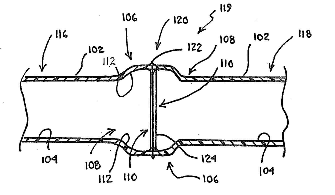
Specifically, due to the heat and pressure required to melt and fuse the conduit, when the terminal ends of two pipe sections are melted and engaged, the engagement pressure results in the creation of a bead at the joint area extending from both the internal wall and external wall of the now-fused pipe.
Further, the presence of such an internal bead may interfere with and impact certain objects inserted therein, e.g., communication, power and data wiring, etc.
For example, the bead may damage the insulation layer of the wire, which may detrimentally affect the wire signal, or cause short circuits in the

Method used


Image

  • Conduit, manufacture thereof and fusion process therefor
  • Conduit, manufacture thereof and fusion process therefor
  • Conduit, manufacture thereof and fusion process therefor

Examples


Example

[0023]For purposes of the description hereinafter, the terms “upper”, “lower”, “right”, “left”, “vertical”, “horizontal”, “top”, “bottom”, “lateral”, “longitudinal” and derivatives thereof shall relate to the invention as it is oriented in the drawing figures. However, it is to be understood that the invention may assume various alternative variations and step sequences, except where expressly specified to the contrary. It is also to be understood that the specific devices and processes illustrated in the attached drawings, and described in the following specification, are simply exemplary embodiments of the invention. Hence, specific dimensions and other physical characteristics related to the embodiments disclosed herein are not to be considered as limiting.

[0024]Various numerical ranges are disclosed in this patent application. Because these ranges are continuous, they include every value between the minimum and maximum values. Unless expressly indicated otherwise, the various nu...


PUM

PropertyMeasurementUnit
Fractionaaaaaaaaaa
Timeaaaaaaaaaa
Pressureaaaaaaaaaa

Abstract

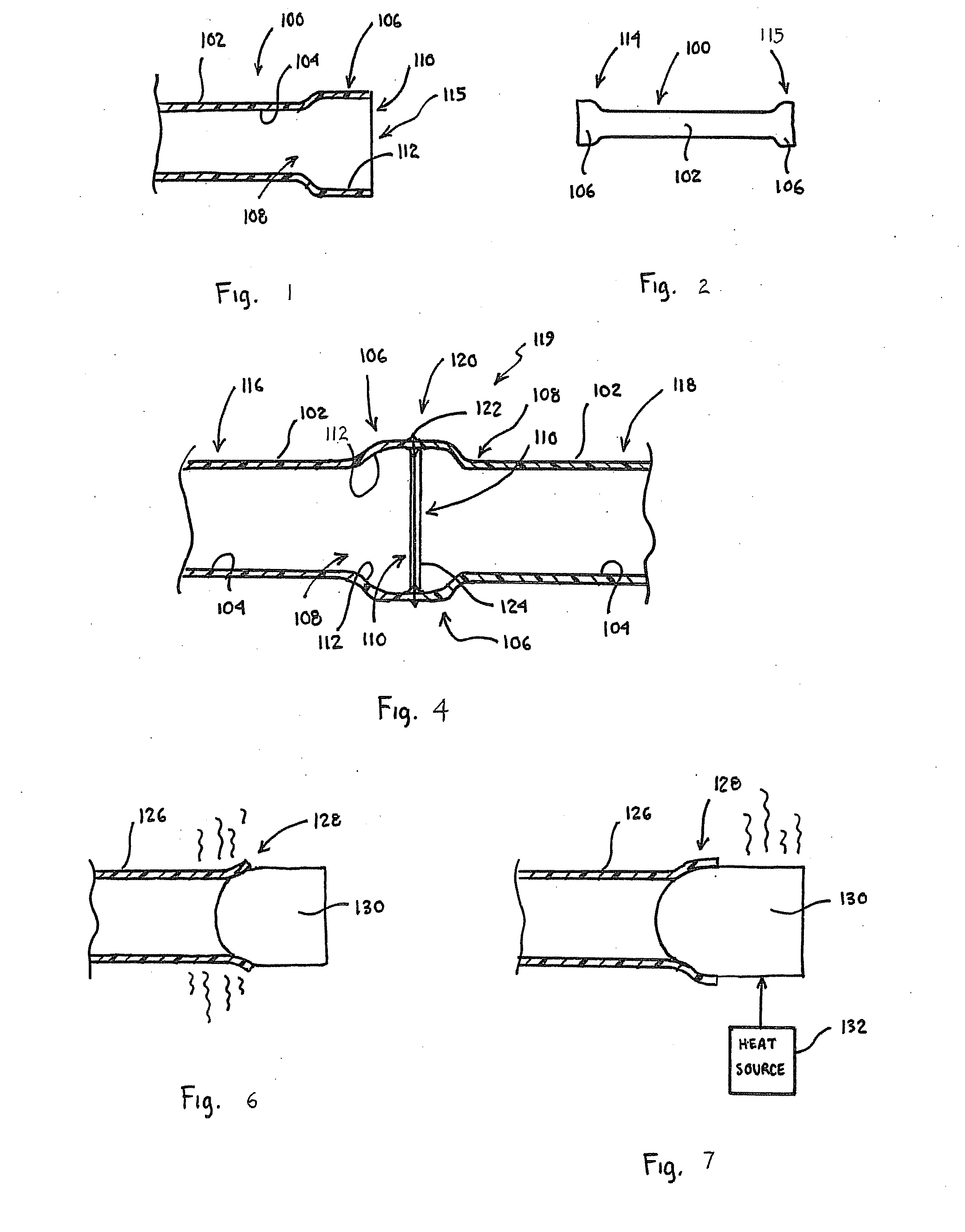
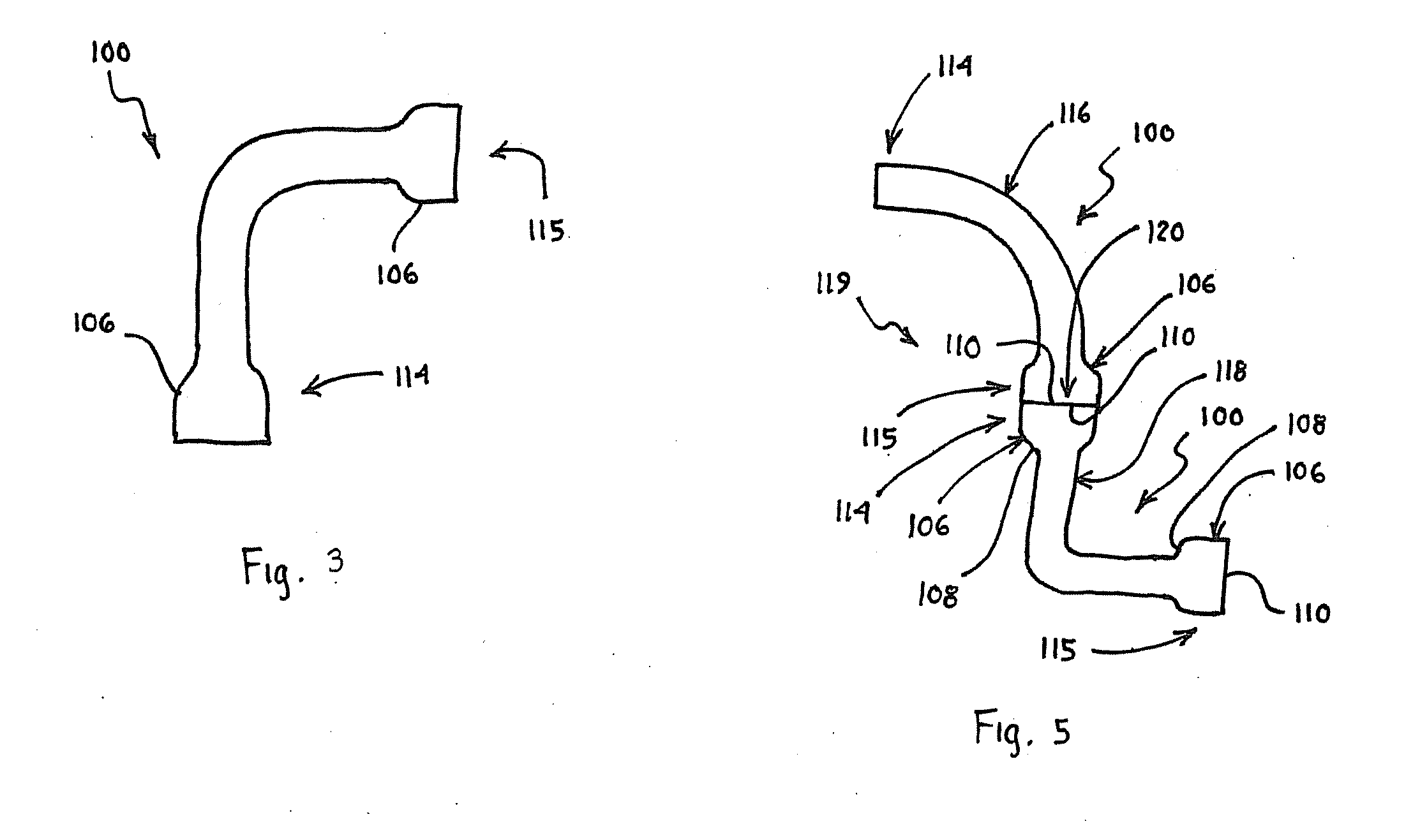
A method for fusing a first conduit section to a second conduit section, each including at least one bell portion with a first end and a second end and having a bell portion inside dimension greater at the second end of the bell portion than at the first end of the bell portion. The method includes: heating and melting at least a portion of each of the second end of the bell portion of the first conduit section and the second end of the bell portion of the second conduit section; and fusing the first conduit section and the second conduit section by engaging the second end of the bell portion of the first conduit section with the second end of the bell portion of the second conduit section, thereby creating a fused conduit system having a fused joint area.

Description

CROSS REFERENCE TO RELATED APPLICATIONS[0001]This application claims the benefit of priority of U.S. Provisional Patent Application Ser. No. 60 / 923,298, filed Apr. 13, 2007, which is herein incorporated by reference in its entirety.BACKGROUND OF THE INVENTION[0002]1. Field of the Invention[0003]The present invention relates generally to systems for fusing or joining conduit or piping sections, such as polyvinyl chloride conduit or piping, and in particular, to a fusion process for effectively and permanently joining a first conduit section to a second conduit section, as well as a fused conduit, a fused joint area, and methods of manufacturing a conduit.[0004]2. Description of Related Art[0005]Conduit systems are used in many applications throughout the world in order to transfer or convey material, such as water and other fluids, from location to location for distribution throughout the system. In addition, conduit systems are also utilized as a structural enclosure for communicati...

Claims


Application Information

Patent Timeline
IPC IPC(8): E21B7/04F16L13/02
CPCB29B13/025Y10T29/49227B29C65/028B29C65/20B29C66/1142B29C66/3242B29C66/5221B29C66/81422B29K2023/06B29K2023/065B29K2027/06B29K2101/12B29L2023/00B29L2023/004F16L47/02B29C57/02B29C66/92211H02G3/04B29C66/91431B29C66/91423B29C66/91421B29C66/949B29C66/929B29C65/2015B29C65/2092B29C66/0224B29C66/322B29C66/522B29C66/5223B29C66/71B29C66/73921B29C65/00
Inventor BECKER, WILLIAM F.MARTI, THOMASKERNER, ERICBENVENUTI, MICHAELMCKANNA, MICHAELURBANEK, DOUGLAS
Owner UNDERGROUND SOLUTIONS TECH GROUP
Why Eureka
Try Eureka