Walking Robot by Using Passive Changes in Joint Angles and Control Method Thereof

a technology of joint angle and control method, applied in the field of robots, can solve the problems of difficulty in controlling walking, change in walking state, disturbance of stride, etc., and achieve the effect of natural walking movement, low energy consumption, and high degree of safety

Inactive Publication Date: 2008-10-23
HASEGAWA YASUHISA +2
View PDF8 Cites 9 Cited by
  • Summary
  • Abstract
  • Description
  • Claims
  • Application Information

AI Technical Summary

Benefits of technology

[0026]According to the method of controlling the robot of the present invention, the robot can walk with the target stride utilizing a phenomenon that naturally changes. This will match well with human walking patterns, and a natural walking movement will be obtained. In addition, the controlling method naturally matches dynamics of the robot, allowing it to wa

Problems solved by technology

In the aforementioned walking control technology, because the robot walks with passive movements, its walking state may change, and the stride thereof

Method used


Image

  • Walking Robot by Using Passive Changes in Joint Angles and Control Method Thereof
  • Walking Robot by Using Passive Changes in Joint Angles and Control Method Thereof
  • Walking Robot by Using Passive Changes in Joint Angles and Control Method Thereof

Examples


Embodiment Construction

[0038]Examples in which the present invention is embodied will be described below with reference to the drawings.

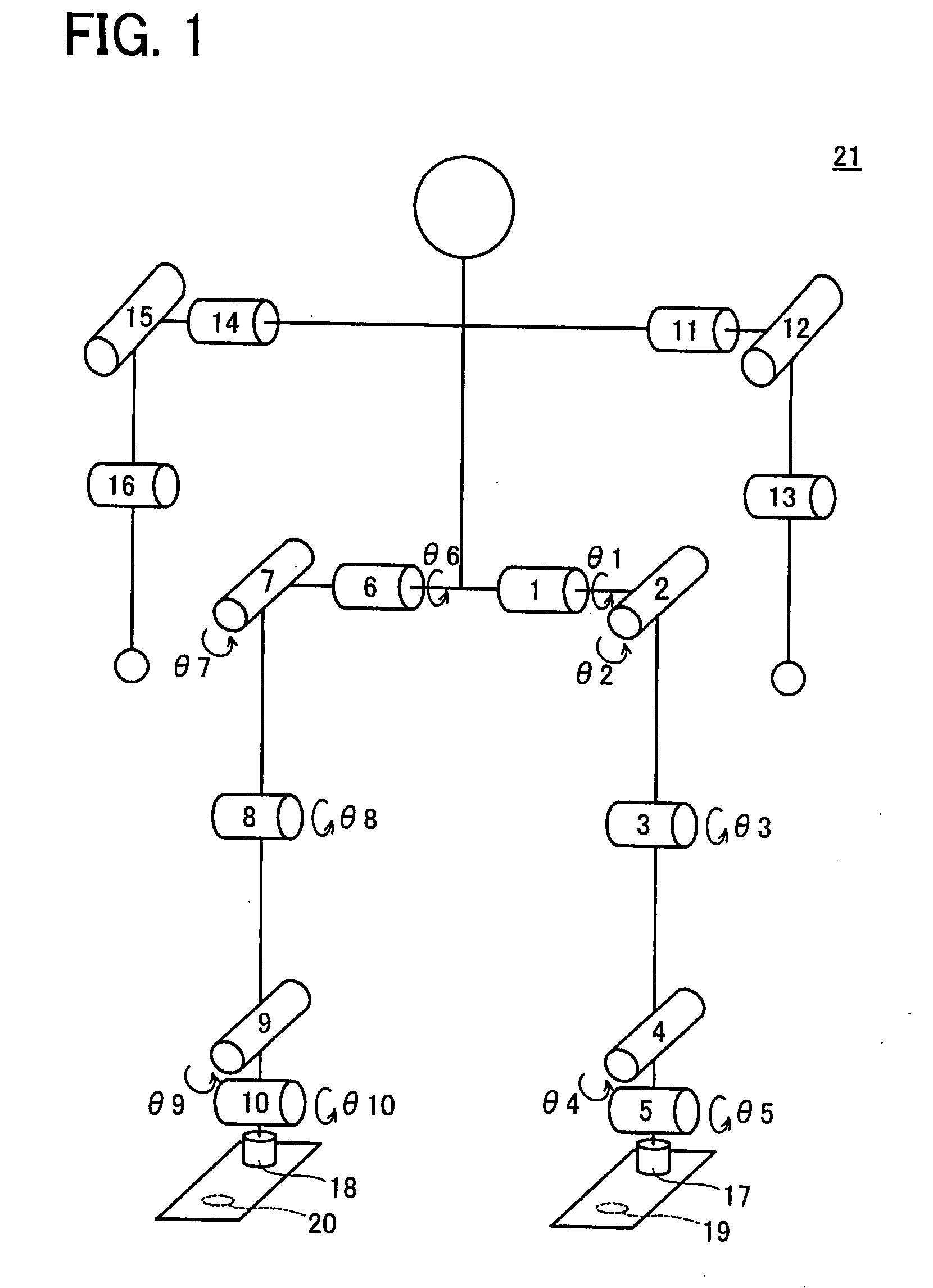
[0039]FIG. 1 shows a mechanical structure of robot 21. The robot 21 comprises a pair of hip joints with two rotation axes, a pair of knee joints with one rotation axis, a pair of ankle joints with two rotation axes, a pair of shoulder joints with two rotation axes, and a pair of elbow joints with one rotation axis. The robot 21 comprises motors having encoders on each rotational axis, and can adjust joint angles and measure joint angles. θ1 to θ10 indicate joint angles. Reference numerals 17, 18 indicate force sensors, and 19, 20 indicate photosensors. The photosensors 19, 20 detect whether the foot plane is grounded or lifted.

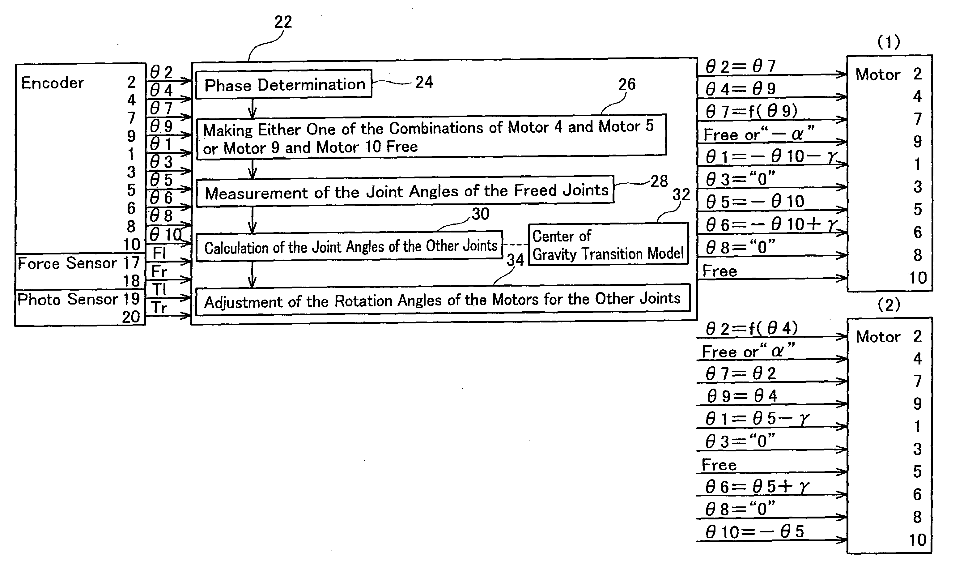
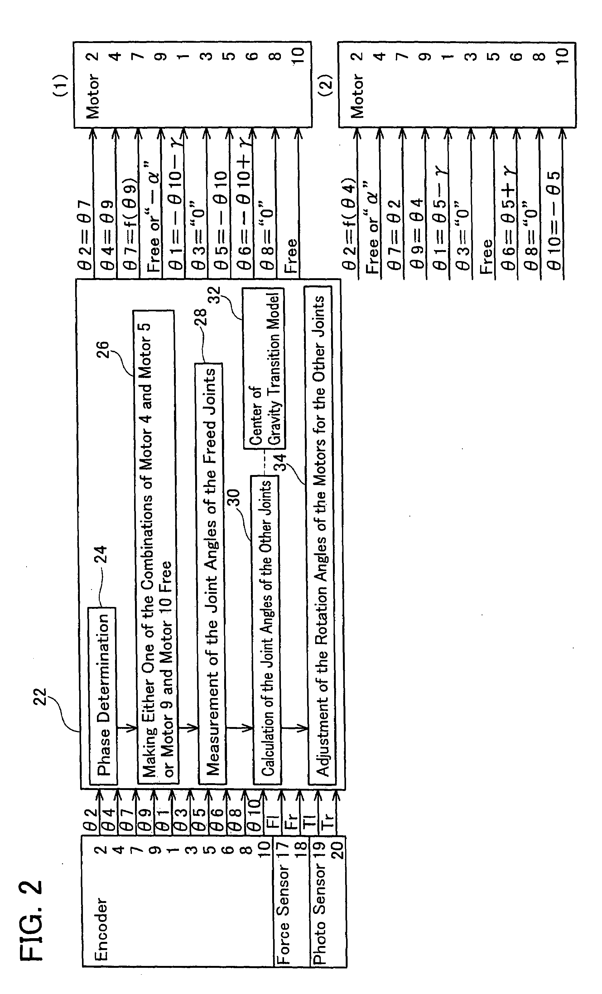
[0040]FIG. 2 shows the components of controller 22 for robot 21. The outputs of encoders 1 to 10, the outputs of force sensors 17, 18, and the output of photosensors 19, 20 are input into controller 22, which instructs rotation angles of motors 1 to...


PUM


Abstract

In a robot with two or more leg links having ankle joint respectively and pivotably linked to a torso, the robot walks naturally by making the ankle joint of a grounded leg link rotate freely by using passive movement. A controller executes controlling operation of calculating target joint angles of remaining joints other than the ankle joint of the grounded leg link based upon the measured joint angles of the ankle joint of the grounded leg link in the lateral and forward direction. The target joint angles of the remaining joints are calculated so as to satisfy the following condition that a tilting angle of the torso matches a target tilting angle determined based upon the measured joint angle of the ankle joint of the grounded leg link in the forward direction, a cycle period of the idle leg link from lifting to grounding, and a target stride of the idle leg link.

Description

CROSS-REFERENCE TO RELATED APPLICATION[0001]The present application claims priority based on Japanese Patent Application No. 2004-267019, filed on Sep. 14, 2004, the entire contents of which are incorporated by reference into this application.TECHNICAL FIELD[0002]The present invention relates to a robot in which two or more leg links are pivotably connected to a torso by means of hip joints, and which walks by pivoting said leg links.BACKGROUND ART[0003]Robots are being developed that walk by changing the relative postures among the left leg link, the hip, and the right leg link. When the relative postures among the left leg link, the hip, and the right leg link are to be changed, the relative postures among the left leg link, the hip, and the right leg link must be changed so that the robot can walk as a result. For this purpose, gait data is used that indicates the positions and postures of the left foot tip, the hip, and the right foot tip respectively.[0004]As shown in FIG. 10, ...

Claims


Application Information

Patent Timeline
IPC IPC(8): B25J9/10
CPCB62D57/032
Inventor FUKUDA, TOSHIOHASEGAWA, YASUHISADOI, MASAHIROSUGA, KEISUKEKAJITANI, YOSHIMI
Owner HASEGAWA YASUHISA
Why Eureka
Try Eureka