Charging display system

a display system and charging technology, applied in the field of charging systems, can solve the problems of inconvenient distribution of such portable consumer electronic devices, devices that require more frequent recharging, and battery and other energy storage technologies that have not kept pace with the miniaturization trend

Active Publication Date: 2008-10-23
APPLE INC
View PDF11 Cites 326 Cited by
  • Summary
  • Abstract
  • Description
  • Claims
  • Application Information

AI Technical Summary

Problems solved by technology

Unfortunately, battery and other energy storage technologies have not kept pace with this miniaturization trend.
This means that such devices require more frequent recharging and that such devices often require recharging on a daily basis.
It is often inconvenient to distribute such portable consumer electronic devices for charging each day and to collect such devices when it is time to leave the home.
This makes it increasingly difficult to present all of the status information regarding the electronic device on such smaller displays at one time.
Further, the average size of a person's fingers and the average dexterity in the use of a person's fingers has not improved in concert with the miniaturization of controls on such devices.
This leads to frustration during the operation of the device.
Either of these trends makes such consumer electronic devices more difficult to interact with.
Further, if a compact electronic device is configured for charging and synchronization with a particular computer, and that computer is in use by another user, even wireless data transfer would have to wait until the computer was available.

Method used


Image

  • Charging display system
  • Charging display system
  • Charging display system

Examples


Embodiment Construction

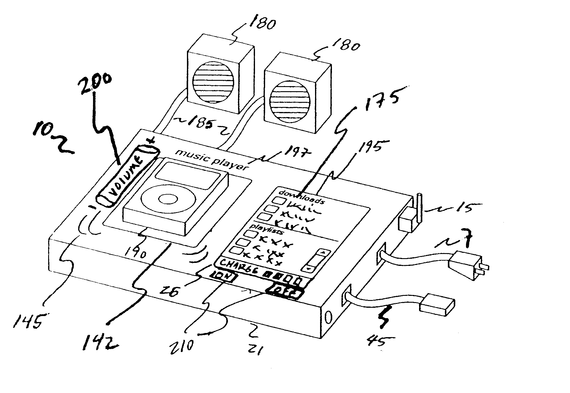
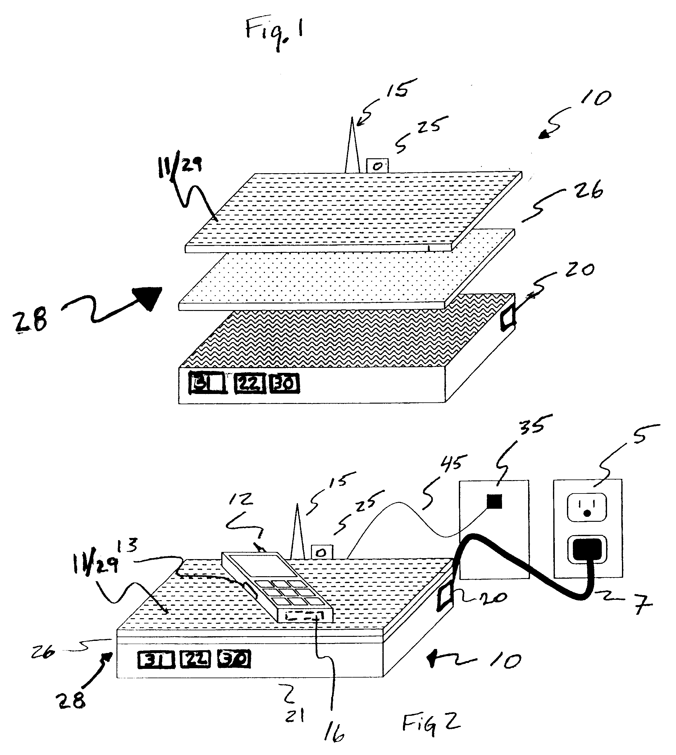
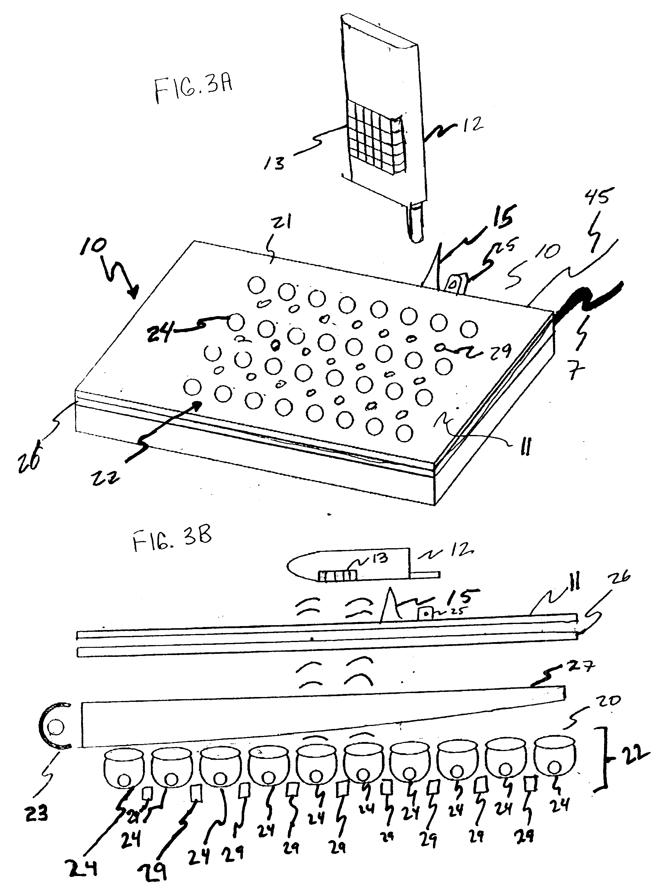
[0027]FIG. 1 illustrates an exploded perspective view of one embodiment of a charging display system 10, while FIG. 2 illustrates a perspective view of the embodiment of FIG. 1 in an unexploded view and with a wirelessly rechargeable device 12 positioned thereon. In the embodiment that is illustrated in FIGS. 1 and 2, charging display system 10 has a contact surface 11 against which a power receiving element 13 of a rechargeable device 12 can be positioned. A wireless charging system 20 receives power from a power source 5, illustrated here as an AC receptacle that is connected to wireless charging system 20 by way of a power cord 7 which includes a power signal generator circuit 22 that converts the received power into a power signal that travels through contact surface 11 and that is received by a power receiving element 13. Power receiving element 13 has a transducer circuit or other power signal receiving circuit that receives the power signal and that converts the power signal ...


PUM


Abstract

A charging display system and method for operating a display system are provided with the method comprising sensing the presence of a wirelessly rechargeable device proximate to or on a surface through which a presentation area of a display can present image information; identifying a type of the wirelessly rechargeable device; obtaining device representation having features that are related to a portion of the presentation area that can be occupied by the presence of the identified type of rechargeable device; determining a position and orientation of the rechargeable device proximate to or on the surface; and segmenting the presentation area into a wirelessly rechargeable device portion and a graphic presentation portion outside of the determined of the rechargeable device portion. A wireless power signal is transmitted through the rechargeable device portion and graphic information related to the rechargeable device is displayed in the graphic presentation portion.

Description

FIELD OF THE INVENTION[0001]The invention relates to charging systems that charge rechargeable devices.BACKGROUND OF THE INVENTION[0002]A continuing trend in consumer electronic devices such as portable music players, cellular phones, computers, cameras, key chains with storage memory and the like is reduced size. Largely, this trend has been made possible through advances in the miniaturization of the electronic components of such devices. This trend has led, for example, to the creation of consumer electronic devices that are scaled on the order of a few centimeters. Such small-scale devices enable consumers to carry a vast array of electronic capabilities with them.[0003]Unfortunately, battery and other energy storage technologies have not kept pace with this miniaturization trend. Accordingly, as the size of the device has been reduced, smaller batteries are being incorporated into such portable consumer electronic devices. This means that such devices require more frequent rech...

Claims


Application Information

Patent Timeline
Patent Type & Authority Applications(United States)
IPC IPC(8): H02J7/00
CPCH02J7/025H02J7/0042G06F1/266G06F1/1632H02J50/402H02J7/0044H02J50/80H02J50/90H02J50/10H02J7/0047H02J50/40H02J50/60H02J2310/22
Inventor MANICO, JOSEPH A.LAWTHER, JOEL S.TELEK, MICHAEL J.
Owner APPLE INC
Why Eureka
Try Eureka