
Motor having improved mechanism

Inactive Publication Date: 2008-10-23
VICTOR CO OF JAPAN LTD
View PDF2 Cites 21 Cited by
  • Summary
  • Abstract
  • Description
  • Claims
  • Application Information

AI Technical Summary

Benefits of technology

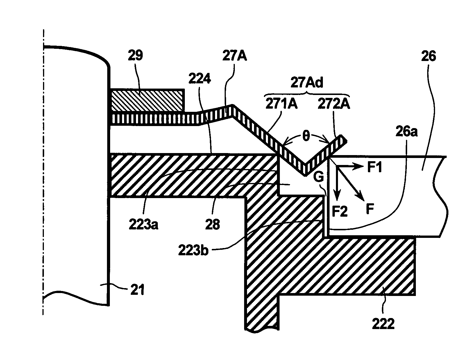
[0017]Accordingly, in consideration of the above-mentioned problems of the prior arts, an object of the present invention is to provide a motor having improved mechanism, which enables to retain a body of revolution such as a polygon mirror stably and to rotate the body of revolution in higher rotational speed without unbalancing the revolution.

Problems solved by technology

Particularly, pressure force in the radial direction acting on the polygon mirror Pm1 changes, and resulting in a problem such that coaxial accuracy of the polygon mirror Pm1 is deteriorated.
In other words, according to the Japanese publication of unexamined patent applications No. 2006-187970, the mirror holding spring is hard to be processed or manufactured in higher accuracy.
The defective accuracy makes pressure force in the radial direction of the polygon mirror vary.
Accordingly, the motor is not suitable for a polygon mirror motor to rotate a polygon mirror in a higher rotational speed without unbalancing the revolution of the polygon mirror.
Accordingly, the phenomenon generates further problem such that revolution of the polygon mirror Pm2 is made unstable.

Method used


Image

  • Motor having improved mechanism
  • Motor having improved mechanism
  • Motor having improved mechanism

Examples


first embodiment

[0032]In reference to FIGS. 1-6, a motor having improved mechanism according to a first embodiment of the present invention is detailed next. In this embodiment, description is given to a polygon mirror motor as an example of a motor having improved mechanism. However, the motor having improved mechanism enables to be applied for an HDD (hard disc drive) motor, which rotates a hard disc as a body of revolution, and a disc driving motor, which rotates discs other than a hard disc.

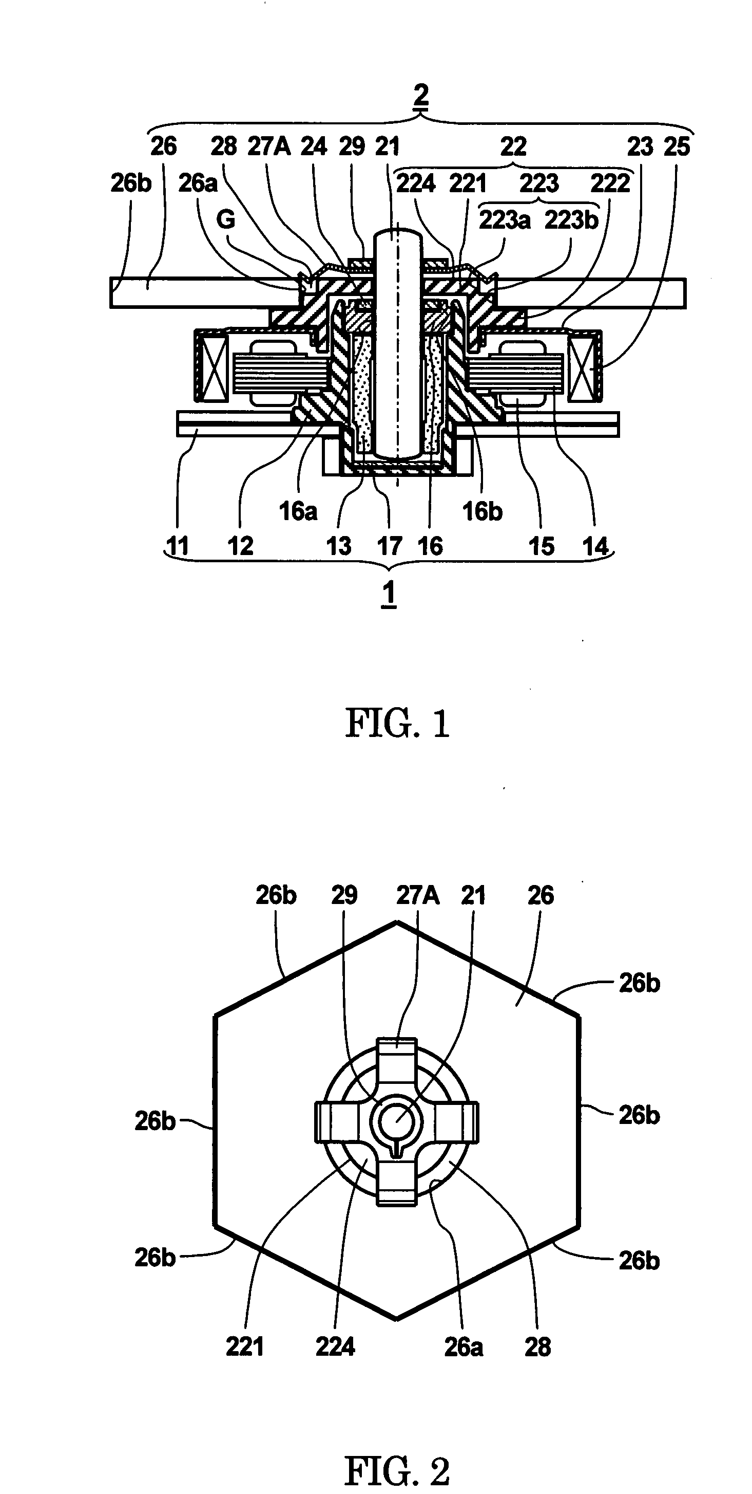
[0033]FIG. 1 is a cross sectional view of a motor having improved mechanism according to a first embodiment of the present invention.

[0034]FIG. 2 is a plan view of the motor having improved mechanism shown in FIG. 1 exhibiting a holding state of a polygon mirror according to the first embodiment of the present invention.

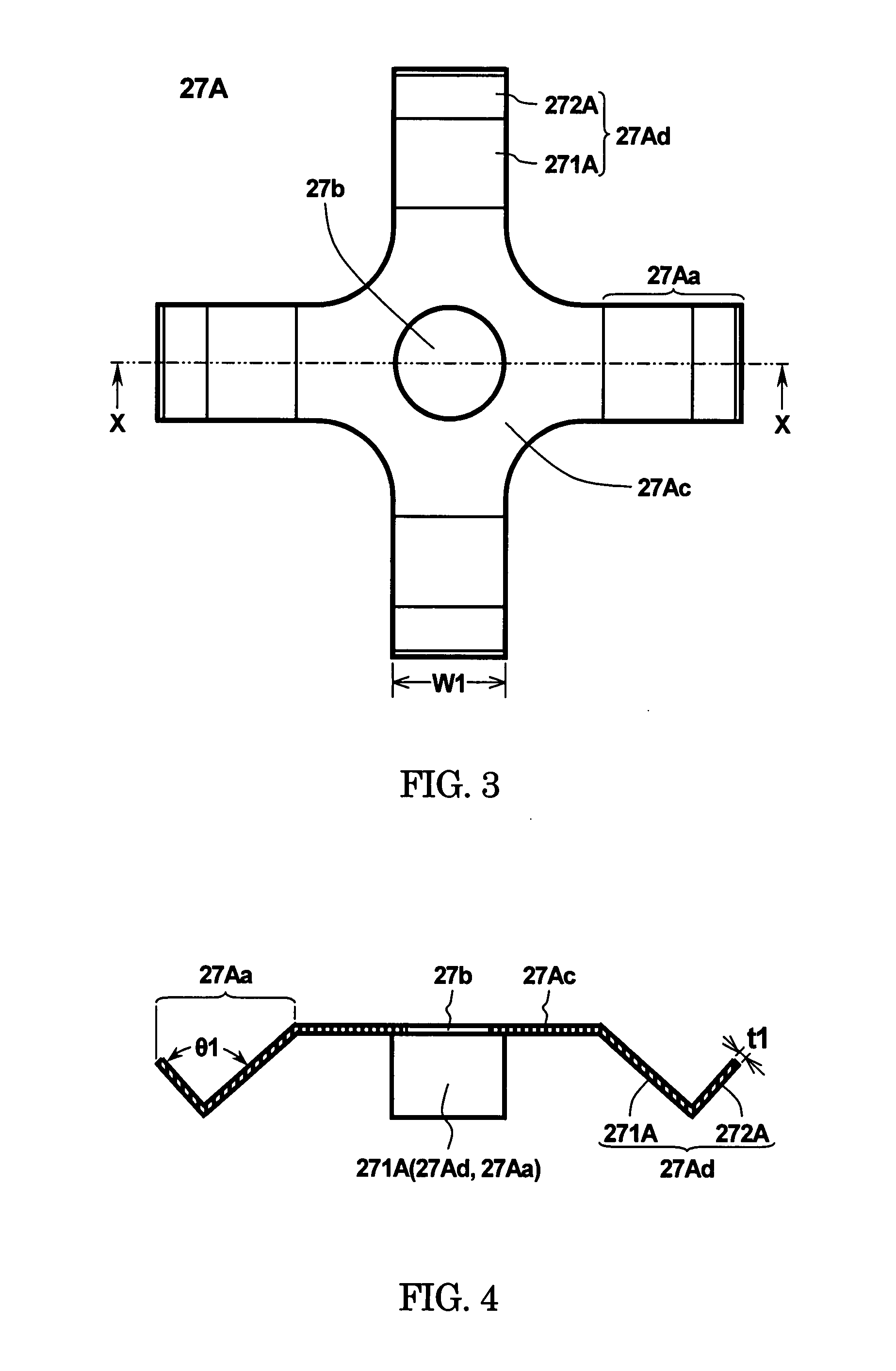
[0035]FIG. 3 is an enlarged plan view of a first elastic plate holding the polygon mirror in place according to the first embodiment of the present invention.

[0036]FIG. 4 is a cross sectional...

second embodiment

[0081]FIG. 7(a) is a plan view of a second elastic plate according to a second embodiment of the present invention.

[0082]FIG. 7(b) is a cross sectional view of the second elastic plate taken substantially along line Y-Y of FIG. 7(a).

[0083]A motor having improved mechanism (hereinafter generically referred to as a motor) according to a second embodiment of the present invention is identical to the motor according to the first embodiment except for the first elastic plate 27A, so that details of the motor according to the second embodiment other than a second elastic plate 27B are omitted.

[0084]In the case of the first embodiment of the present invention, the first elastic plate 27A is provided with four arm sections 27Aa. However, the number of arm sections 27Aa is not limited to be four. For instance, as shown in FIG. 7(a), the second elastic plate 27B enables to be provided with five arm sections 27Ba that extend radially from the center of a flat section 27Bc having a center hole ...

third embodiment

[0089]FIG. 8(a) is a perspective view of a third elastic plate according to a third embodiment of the present invention.

[0090]FIG. 8(b) is a cross sectional view of the third elastic plate shown in FIG. 8(a).

[0091]A motor having improved mechanism (hereinafter generically referred to as a motor) according to a third embodiment of the present invention is identical to the motor according to the first embodiment except for the first elastic plate 27A, so that details of the motor according to the third embodiment other than a third elastic plate 27C are omitted.

[0092]In the case of the first embodiment of the present invention, the first elastic plate 27A is provided with four arm sections 27Aa. However, the number of arm sections 27Aa is not limited to be four. In the case of the third embodiment, as shown in FIG. 8(a), the third elastic plate 27C is formed in a cup shape in which first and second slanting sections are continuously disposed in the circumferential direction without an...


PUM


Abstract

A motor having improved mechanism is composed of a body of revolution having a mounting hole in the center of the body; a rotor hub having a boss section to be inserted into the mounting hole of the body of revolution and a flange section supporting the body of revolution; and an elastic plate installed coaxially to the rotor hub and pressing the body of revolution on the flange section of the rotor hub, wherein the elastic plate is provided with a plain section having a hole in the center and a plurality of arm sections extending radially from an outer circumference of the plain section, and wherein each of the arm sections is provided with a first slanting section that is inclined with respect to the plain section and a second slanting section having an angle of gradient different from that of the first slanting section, and further wherein the first slanting section contacts with an outer circumferential edge of the boss section that confronts with an inner wall surface of the mounting hole of the body of revolution and the second slanting section contacts with a top end edge of the inner wall surface of the mounting hole.

Description

BACKGROUND OF THE INVENTION[0001]1. Field of the Invention[0002]This invention relates to a motor having improved mechanism for rotating a polygon mirror and a recording medium in disciform such as a hard disc, particularly, relates to a motor having improved mechanism suitable for retaining a body of revolution such as a polygon mirror so as to be balanced well.[0003]2. Description of the Related Art[0004]Generally, it is required for motors to be used in precision instruments as a driving source that the motors should exhibit excellent rotational performances high in accuracy without any unbalanced revolution. In the case of a polygon mirror motor to be used in a laser beam printer (LBP), for instance, the polygon mirror motor is required to retain a polygon mirror as a body of revolution so as to be concentric with a rotor shaft and to rotate the polygon mirror in higher rotational speed without unbalancing the revolution.[0005]One example of such a polygon mirror motor (polygon ...

Claims


Application Information

Patent Timeline
IPC IPC(8): F16C17/08G02B26/10
CPCF16D3/77G02B26/121H02K5/24H02K5/00
Inventor NISHINO, HIROTAKEKAMIJO, JUNICHI
Owner VICTOR CO OF JAPAN LTD
Learn More