
Auto stabilization method and photographing apparatus using the same

a technology of auto stabilization and photographing apparatus, which is applied in the field of auto stabilization method and photographing apparatus using the same, can solve the problems of degrading performance compared to optical compensation, piezo-electric element may contract too fast for the photographing element to follow, and inefficient compensating for hand tremor by lens driving

Inactive Publication Date: 2008-10-23
SAMSUNG ELECTRONICS CO LTD
View PDF6 Cites 3 Cited by
  • Summary
  • Abstract
  • Description
  • Claims
  • Application Information

AI Technical Summary

Benefits of technology

The present invention provides an auto stabilization method for a photographing apparatus that compensates for hand tremor. The method includes generating a driving element control signal to compensate for vibration caused by hand tremor based on the dynamic characteristics of the driving unit, such as sensitivity deterioration in low frequency band, sensitivity enhancement in high frequency band, position, and size of input. The method also includes adding a driving unit movement compensation signal to control displacement of the driving unit to the driving unit control signal. The invention also provides an auto stabilization unit and a photographing apparatus with the auto stabilization method. The technical effects of the invention include reducing displacement saturation or delay of movement caused by surface illumination of the ball guide and position, and ensuring linearity among frequency responses of the driving element.

Problems solved by technology

Compensating for hand tremor by lens driving is inefficient for a compact and light apparatus, due to non-linearity of a lens in an optical compensation, and its requirement for a driving lens in a lens barrel.
However, this method has fluctuation of compensation accuracy depending on the respective algorithm employed for signal processing, and has degraded performance compared to an optical compensation.
Although the photographing element mounted on a rotary axis moves along, when the piezo-electric element is expanded gradually, the piezo-electric element may contract too fast for the photographing element to follow.
Accordingly, SIDM using a piezo-electric element has low responsiveness, and although it uses ultrasonic waves, SIDM may have a high frequency noise.
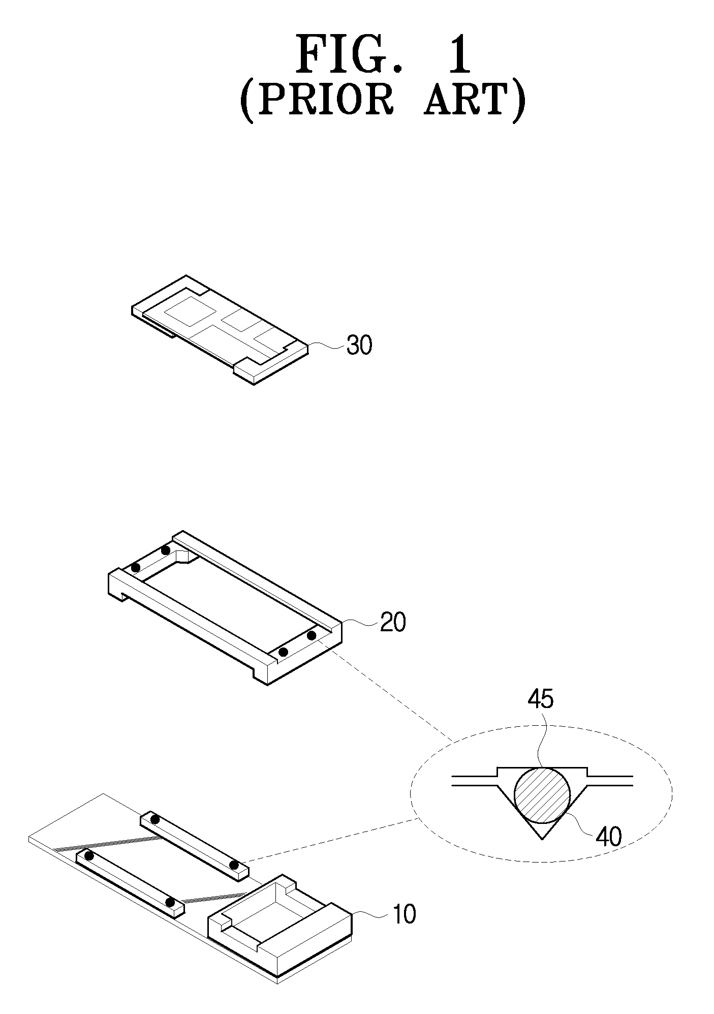
If a hand tremor compensation mechanism is not employed, additional structures such as a latch to fix a driving system are required, which is inappropriate for a compact and light apparatus.

Method used


Image

  • Auto stabilization method and photographing apparatus using the same
  • Auto stabilization method and photographing apparatus using the same
  • Auto stabilization method and photographing apparatus using the same

Examples


Embodiment Construction

[0058]Reference will now be made in detail to embodiments of the present general inventive concept, examples of which are illustrated in the accompanying drawings, wherein like reference numerals refer to the like elements throughout. The embodiments are described below in order to explain the present general inventive concept by referring to the figures.

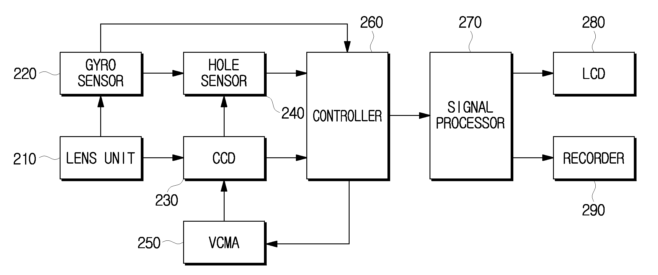
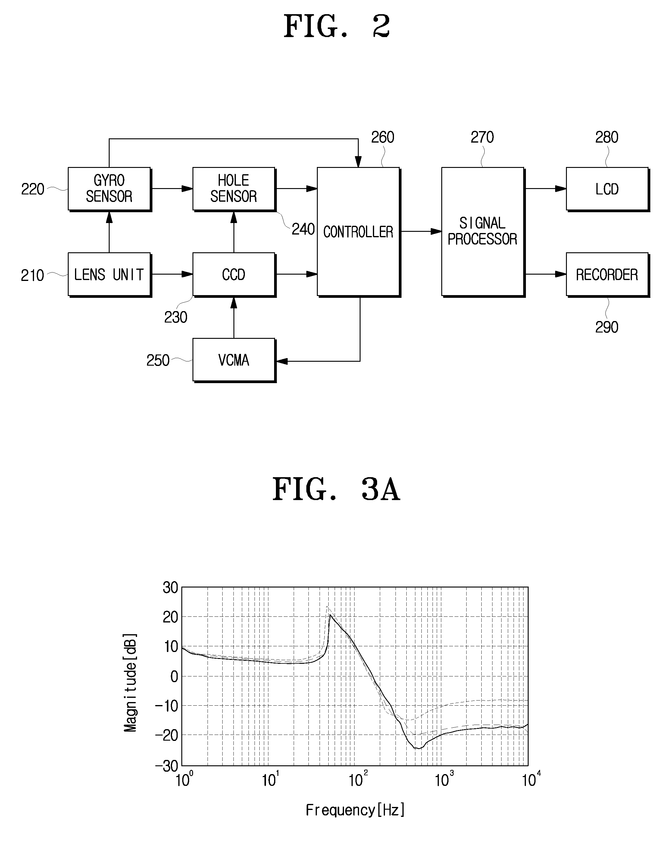
[0059]FIG. 2 is a block diagram illustrating a photographing apparatus according to the present general inventive concept.

[0060]A photographing apparatus according to the present general inventive concept adopts a photographing element driving method as an auto stabilization of hand tremor, and employs a voice coil motor actuator (VCMA) to drive a photographing element. The photographing apparatus controls hand tremor compensation in consideration of dynamic characteristic of a VCMA structure, and thus provides improved compensation.

[0061]Referring to FIG. 2, the photographing apparatus according to the present general inventive con...


PUM


Abstract

An auto stabilization method and a photographing apparatus using the same are provided. The photographing apparatus having the auto stabilization function includes a voice coil motor actuator (VCMA) to move a photographing element. In the generation of hand tremor, the photographing apparatus controls compensating of the hand tremor. Because one or more dynamic characteristics according to a structure of the VCMA is considered, saturation or delay of displacement of the VCMA is avoided, and a clearer image is provided.

Description

CROSS-REFERENCE TO RELATED APPLICATIONS[0001]This application claims priority under 35 U.S.C. §119(a) from of Korean Patent Application No. 10-2007-0037456, filed on Apr. 17, 2007, in the Korean Intellectual Property Office, the disclosure of which is hereby incorporated herein in its entirety by reference.BACKGROUND OF THE INVENTION[0002]1. Field of the Invention[0003]The present general inventive concept relates to an auto stabilization method and a photographing apparatus using the same. More particularly, the present general inventive concept relates to an auto stabilization method to compensate for hand tremor according to a driving characteristic of a photographing element employed in a photographing apparatus, and a photographing apparatus using the same.[0004]2. Description of the Related Art[0005]Generally, hand tremor of a photographing apparatus is generally compensated for by compensation of divergence of an optical axis due to vibration by driving a lens, compensation b...

Claims


Application Information

Patent Timeline
Patent Type & Authority Applications(United States)
IPC IPC(8): G03B17/00H04N23/40
CPCG03B5/00G03B2205/0007G03B2217/005H04N5/23248H04N5/23258G03B2205/0069H04N23/68H04N23/6812
Inventor YEOM, DONG-HAESEO, JOONG-EONJUNG, SOO-YULPARK, NAM-JOON
Owner SAMSUNG ELECTRONICS CO LTD
Learn More