
Injection Molding Machine

a molding machine and injection molding technology, applied in the field of injection molding machines, can solve the problems of bending deformation, inability to maintain the parallelism between the stationary plate and the movable plate, and the mold clamping frame becoming larger and heavier, so as to prevent excessive force

Active Publication Date: 2008-10-23
TOYOTA JIDOSHA KK
View PDF5 Cites 0 Cited by
  • Summary
  • Abstract
  • Description
  • Claims
  • Application Information

AI Technical Summary

Benefits of technology

The present invention provides an injection molding machine with a mold clamping frame that is stable and not deformed even if the mold cramping frame deforms. The machine also includes a balancing cylinder to cancel out bending moments caused by the mold clamping cylinder. The mold cramping frame has a first shaft and a second shaft that support the first and second members, preventing excessive force from being exerted on the frame. The first and second shafts slide in the direction in which the movable platen advances and retreats, further preventing excessive force from being exerted on the frame. Overall, the invention provides a stable and reliable injection molding machine.

Problems solved by technology

It is consequently not possible to maintain the parallelism between the stationary platen and the movable platen.
However, the problem with this method is that the mold clamping frame becomes larger and heavier.
Although it is possible to prevent bending moment from being exerted on the connecting member in this conventional injection molding machine, bending moment is exerted on the first and second members, which causes bending deformation thereof.
Compared to the bending deformation of the connecting member, the bending deformation of the first and second members has a smaller effect on the parallelism between the stationary platen and the movable platen, but cannot be ignored if the mold clamping force is greater.
When a mold clamping frame is made smaller and lighter, the bending rigidity of the first and second members consequently decreases, causing the bending deformation of the first and second members to become more severe.
In the conventional injection molding machine, it becomes impossible to maintain the parallelism between the stationary platen and the movable platen when the bending deformation of the first and second members becomes more severe.

Method used


Image

  • Injection Molding Machine
  • Injection Molding Machine
  • Injection Molding Machine

Examples


Embodiment Construction

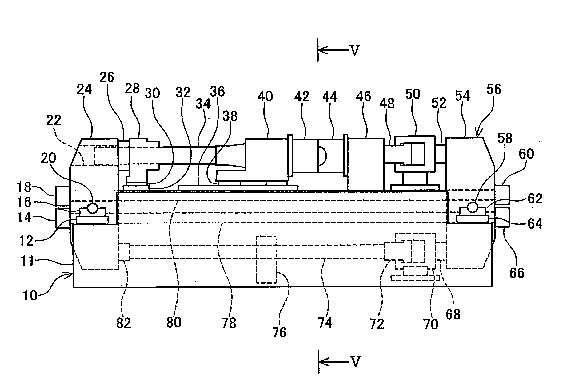
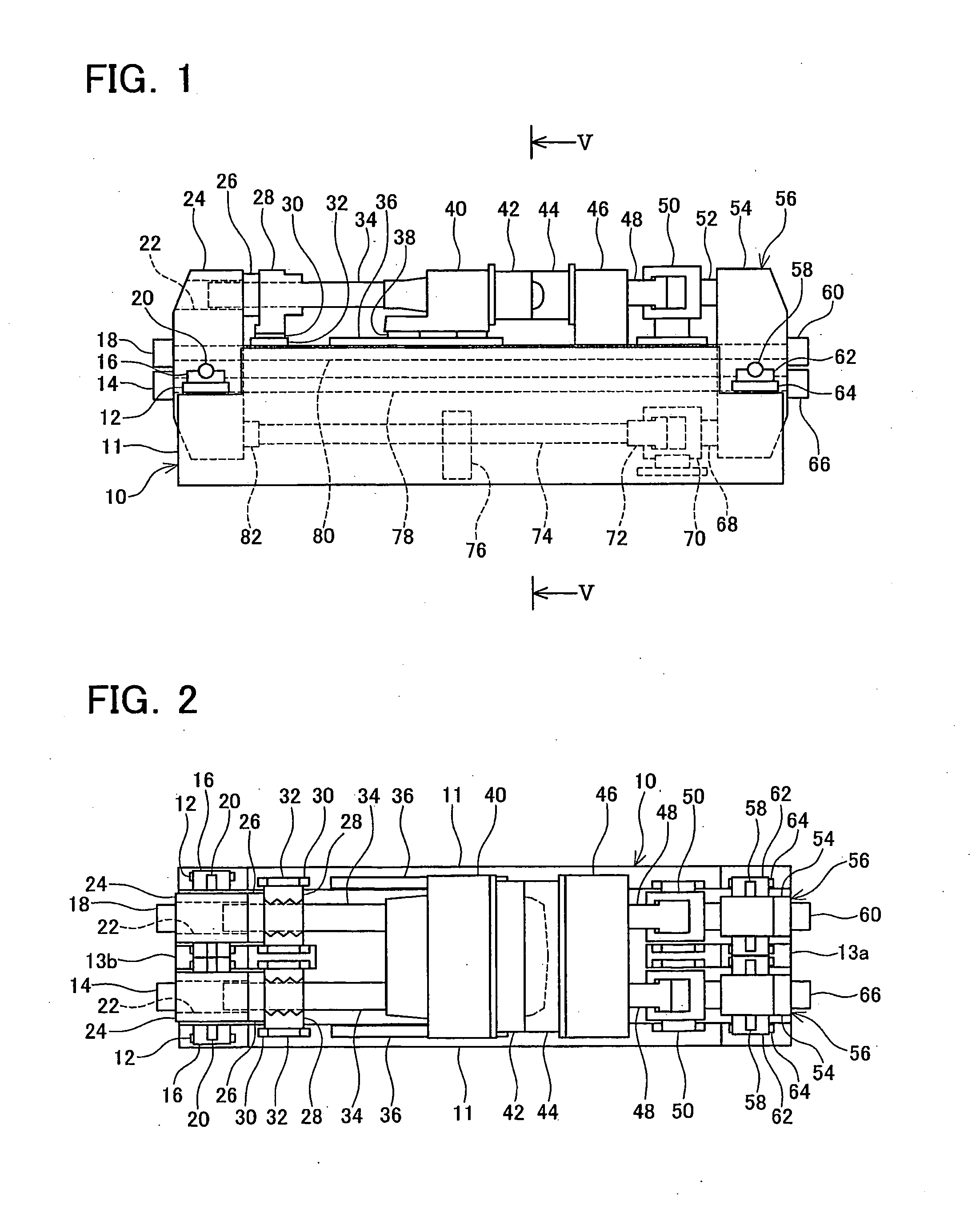
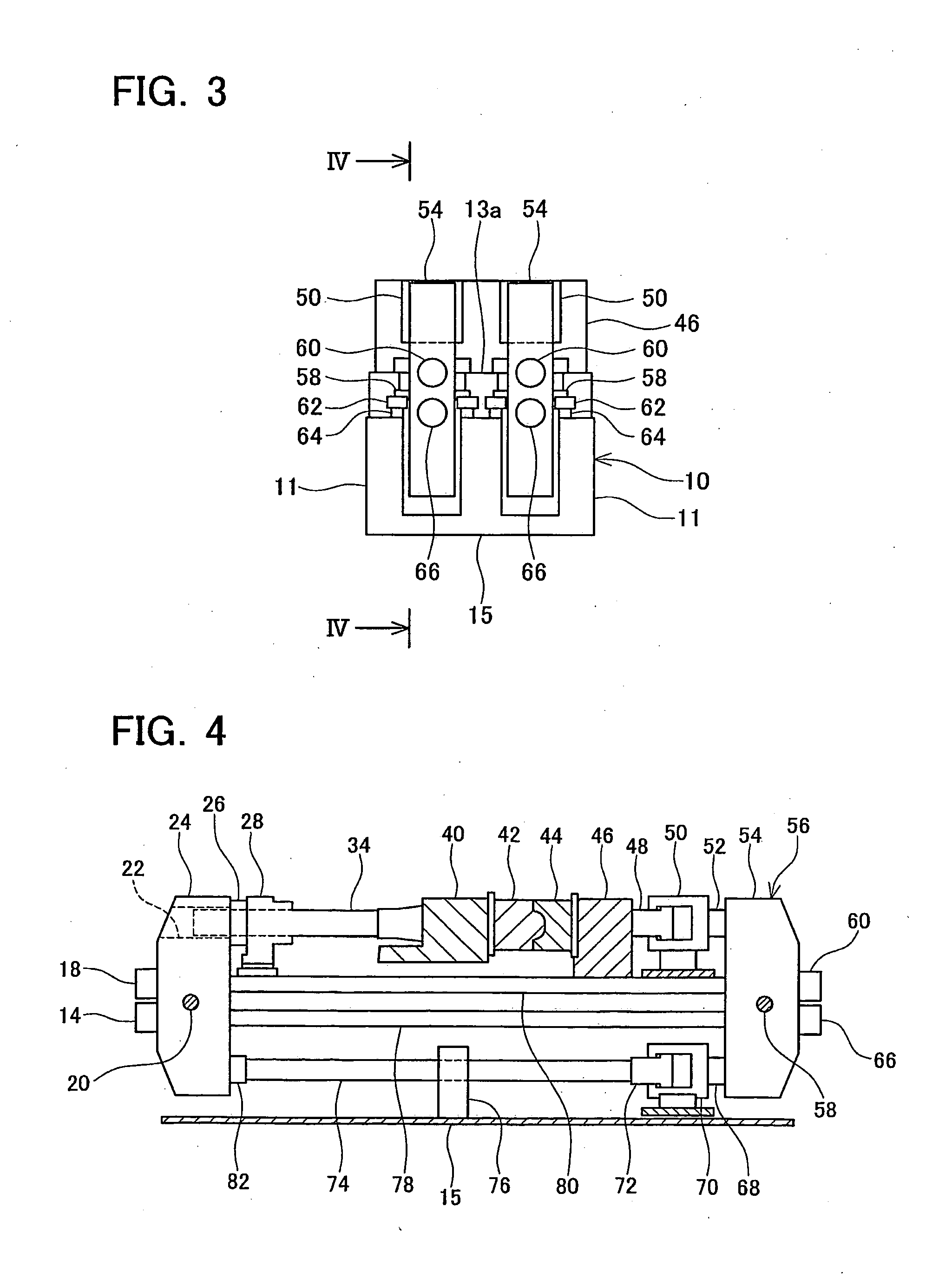
[0020]Next, an injection molding machine according to a detailed representative embodiment of the present invention will be described with reference to FIGS. 1˜5. As shown in FIGS. 1˜5, the injection molding machine comprises a base frame 10, and two mold cramping frames 56, 56.

[0021]As shown in FIG. 2, the base frame 10 has (A) side parts 11, 11 formed at an outer side of the mold cramping frames 56, 56 and parallel with the mold cramping frames 56, 56, and (B) supporting parts 13a and 13b formed between the mold cramping frames 56, 56. Lower edges of the side parts 11, 11 and lower edges of the supporting parts 13a and 13b are connected by a base part 15 (see FIG. 3).

[0022]As shown in FIG. 1, a central part of the side parts 11, 11 is taller than the end parts thereof. A stationary platen 46 is formed on an upper face of the central part of the side parts 11, 11. The stationary platen 46 is fixed such that it cannot move with respect to the side parts 11, 11. A stationary mold 44 ...


PUM

PropertyMeasurementUnit
flexibleaaaaaaaaaa
forceaaaaaaaaaa
clamping forceaaaaaaaaaa

Abstract

An injection molding machine comprises a stationary platen 46 and a movable platen 40. The stationary platen 46 and movable platen 40 may be supported on a base frame 10. A mold cramping frame 56 comprises a first member 54 joined to the stationary platen 46, a second member 24 joined to the movable platen 40, and connecting members 78 and 80 for connecting the first member 54 and the second member 24 at their approximate centers. A mold cramping cylinder 50 is disposed between the first member 54 and the stationary platen 46 or between the second member 24 and the movable platen 40. The stationary platen 46 and the first member 54 are joined in a flexible manner, and the movable platen 40 and the second member 24 are similarly joined in a flexible manner.

Description

TECHNICAL FIELD[0001]This application claims priority to Japanese Patent Application No. 2005-38013 filed on Feb. 15, 2005, the contents of which are hereby incorporated by reference.[0002]The present invention relates to an injection molding machine that has a stationary platen supporting a stationary mold and a movable platen supporting a movable mold.BACKGROUND ART[0003]In an injection molding machine, mold clamping force is usually exerted between a stationary platen and a movable platen during the clamping operation of the stationary mold and the movable mold, and a mold clamping frame receives reactive force of this mold clamping force. A known mold clamping frame (a so-called C-type frame) comprises a first member, a second member facing the first member, and a connecting member that links a lower end of the first member with a lower end of the second member. The first member is connected to a stationary platen, and the second member is connected to a movable platen. In this ...

Claims


Application Information

Patent Timeline
Patent Type & Authority Applications(United States)
IPC IPC(8): B29C45/17B29C45/68
CPCB29C45/1761B29C2045/1768B29C45/17B29C45/68
Inventor AMANO, MASAHIROISOSHIMA, YOSHIHARU
Owner TOYOTA JIDOSHA KK
Learn More