Driving device or image forming apparatus

a technology of forming apparatus and driving device, which is applied in the direction of electrographic process, instruments, gearing, etc., can solve the problems of occupying more space, deteriorating the quality of toner image or image being transferred to recording medium, and pushing up the cos

Inactive Publication Date: 2008-10-23
RICOH KK
View PDF2 Cites 19 Cited by
  • Summary
  • Abstract
  • Description
  • Claims
  • Application Information

AI Technical Summary

Benefits of technology

[0021]It is an object of the present invention to at least partially solve the problems in the conventional technology.

Problems solved by technology

Any variation in the velocity of the photosensitive drum will cause deterioration in the quality of the toner image or of the image being transferred to the recording medium.
However, such a rotary inertial body will occupy more space owing to its size, and owing to its weight, necessitates increasing the rigidity of a supporting mechanism for the rotary inertial body, pushing up the cost.
The size will also hinder accessing the parts beyond to the rotary inertial body for maintenance purpose.
However, here again vibrations occur due to backlash or precision of teeth meshing profile.

Method used


Image

  • Driving device or image forming apparatus
  • Driving device or image forming apparatus
  • Driving device or image forming apparatus

Examples


Embodiment Construction

[0036]Exemplary embodiments of the present invention are explained in detail below with reference to the accompanying drawings.

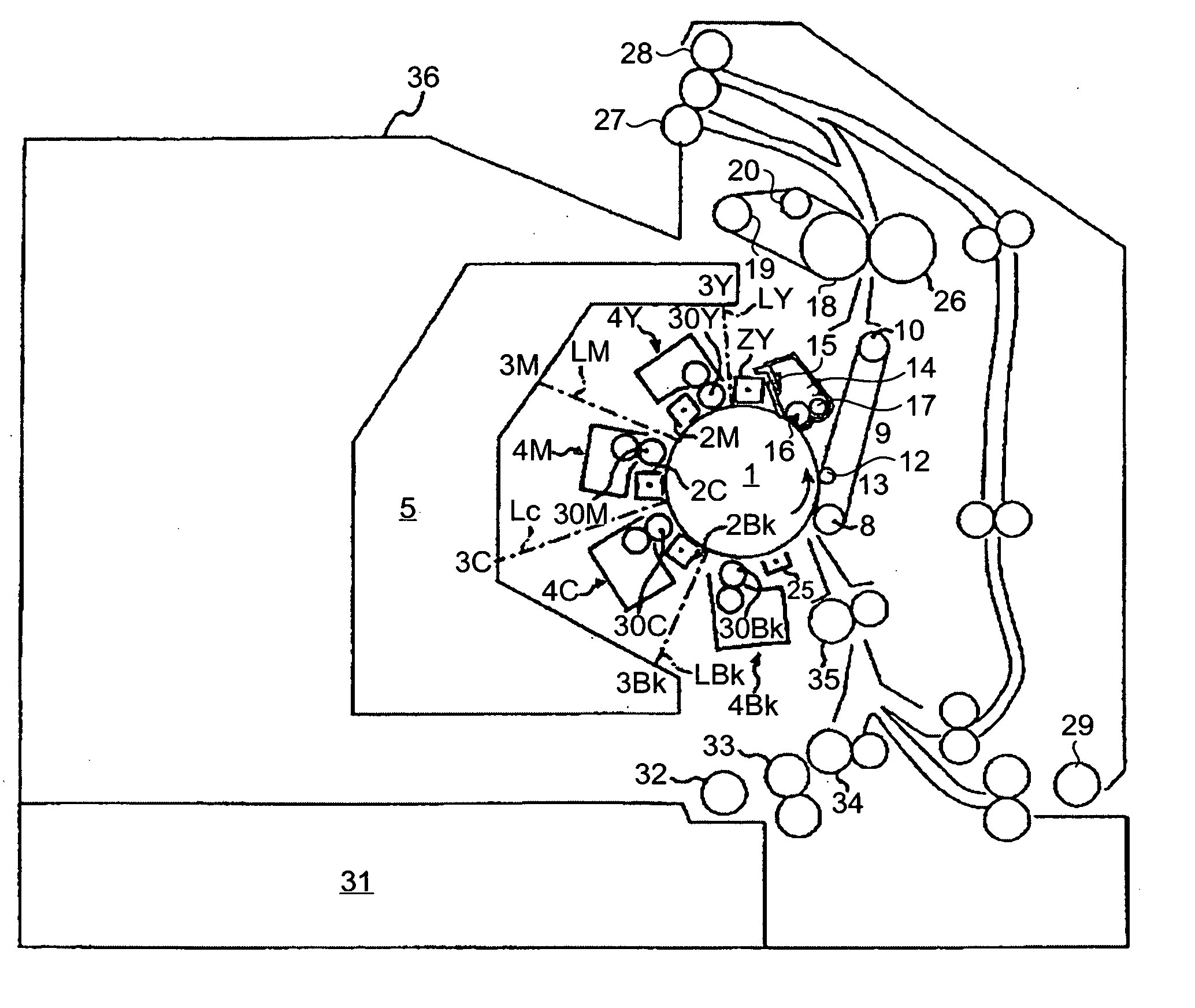
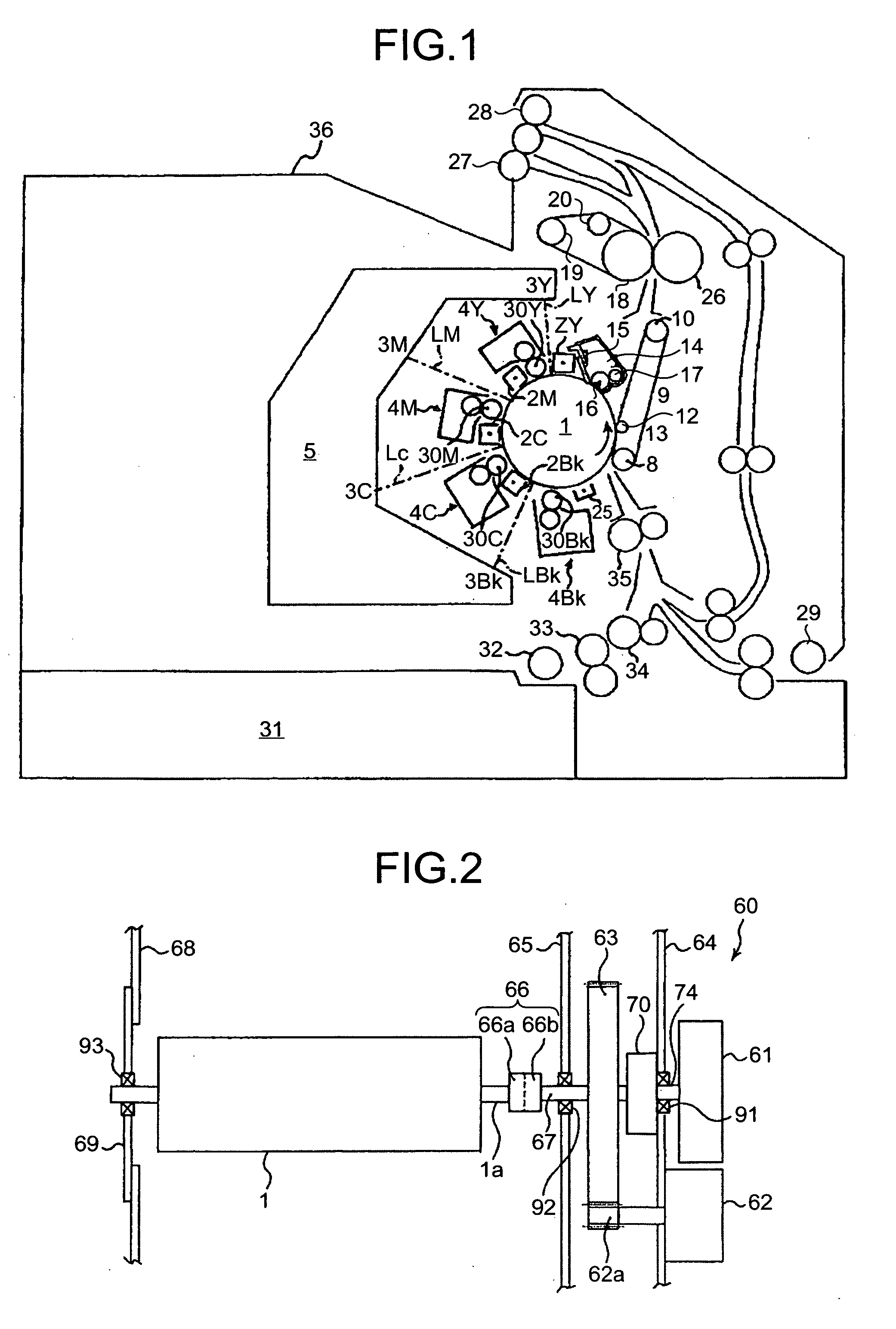
[0037]FIG. 1 is a schematic diagram of an image forming apparatus (a printer) according to an embodiment of the present invention. An image forming unit that takes the central portion of the image forming apparatus includes a photosensitive drum 1 that functions as an image carrying member. One each of a charging device 2 and a developing device for each of the colors yellow (Y), magenta (M), cyan (C), and black (Bk) for forming toner images of the respective colors are arranged around the photosensitive drum 1 in a counter-clockwise direction from the top. To the left of the image forming apparatus is disposed a laser device 5 that illuminates the photosensitive drum 1 with a laser beam L, and illuminates with the laser beam L an exposing unit disposed between each pair of charging device 2 and developing device 4 required for forming a latent image of each...


PUM


Abstract

A rotary-body driving-force transmitting mechanism transmits a driving force from a driving-force source to a rotary body. A rotary-inertial-body driving-force transmitting mechanism transmits the driving force to a rotary inertial body that suppresses a velocity fluctuation in the rotary body. A rotational velocity shift mechanism shifts the rotational velocity. The rotary inertial body, the rotary-body driving-force transmitting mechanism, and the rotary-inertial-body driving-force transmitting mechanism are provided coaxially with a rotary shaft of the rotary body. A satellite frictional gear mechanism is used as the rotational velocity shift mechanism.

Description

CROSS-REFERENCE TO RELATED APPLICATIONS[0001]The present application claims priority to and incorporates by reference the entire contents of Japanese priority document 2007-108590 filed in Japan on Apr. 17, 2007.BACKGROUND OF THE INVENTION[0002]1. Field of the Invention[0003]The present invention relates to a driving device equipped with a rotary inertial body, and an image forming apparatus.[0004]2. Description of the Related Art[0005]Rotary body driving devices that are equipped with a rotary body and a rotary inertial body (flywheel) to maintain a constant rotational velocity of the rotary body are well known. Such rotary body driving devices are widely used as photosensitive drum driving devices in image forming apparatuses such as copiers, facsimile machines, and printers. In an image forming apparatus, image data is written on the photosensitive drum functioning as a rotary body by an optical scanning unit to form a toner image on the photosensitive drum, the toner image is tr...

Claims


Application Information

Patent Timeline
Patent Type & Authority Applications(United States)
IPC IPC(8): G03G15/01F16H3/44
CPCG03G15/757G03G2215/017G03G2221/1657
Inventor MIYAWAKI, KATSUAKIWATANABE, TETSUOTSUKAMOTO, TAKEOAOKI, KATSUHIROYASUTOMI, KEIMARUYAMA, HITOSHIIKEGUCHI, HIROSHI
Owner RICOH KK
Why Eureka
Try Eureka