Unitary Acetabular Cup Prosthesis with Extension for Deficient Acetabulum

a technology of acetabulum and acetabulum, which is applied in the field of orthopedic prosthesis implants, can solve the problems of removing viable and diseased bone, difficult stabilization, and similar problems, and achieves the effects of optimizing the use of available bone, improving stability, and customizing the fi

Inactive Publication Date: 2008-10-23
MICROPORT ORTHOPEDICS HLDG INC
View PDF35 Cites 19 Cited by
  • Summary
  • Abstract
  • Description
  • Claims
  • Application Information

AI Technical Summary

Benefits of technology

[0014]It is an object of the invention to provide an acetabular cup prosthesis that maximizes the use of available bone in a deficient hip to provide improved stability.
[0015]It is an object of the invention to provide an acetabular cup prosthesis that customizes the fit and stability of the cup in deficient acetabulae without requiring excessive reaming of good bone surrounding the deficiency.
[0016]It is an object of the invention to reduce inventory by providing a cup prosthesis that can be used in either a right or left acetabulum of a patient.
[0020]In one preferred embodiment, the flange member has a base portion that extends upward along a portion of the upper rim. The base portion serves to raise a portion of the flange member above the rim, which increases the conformity of the implant to the acetabulum of the patient. A generally planar screw retaining portion extends from the base portion. The screw retaining portion is inclined torn the base portion such that at least a lateral portion of a lower surface of the screw retaining portion is positioned below the upper rim while an upper surface of the screw retaining portion is positioned above the upper rim. The screw retaining portion has a first threaded hole, a second threaded hole and a neutral threaded hole formed therethrough. The neutral threaded hole is positioned between the first and the second threaded holes. The first threaded hole, the neutral threaded hole, and the second threaded hole are fixedly inclined relative to the rim such that the axes of the threaded holes incline toward the axis of the cup portion in a first dimension viewed generally along a width-wise side of the flange member. The axes of the first and second threaded hole are also offset laterally from the axis of the cup portion in a second dimension viewed generally along a length-wise side of the flange member. The axis of the neutral threaded bole is substantially parallel to the axis of the cup portion in the second dimension, such that the neutral threaded hole can be used with either the first or the second threaded hole. The first, second and neutral threaded holes are spaced sufficiently adjacent one another to allow the cup prosthesis to be used in either a left or a right hip of a patient.

Problems solved by technology

However, a larger cup typically requires more reaming than a smaller cup, which may result in removal of viable as well as diseased bone.
In congenital hip dysplasia, portions of the rim of the acetabulum may be minimal and the acetabulum is shallower than normal ft is difficult to stabilize a cup prosthesis in a shallow acetabulum because little bone is available for reaming or for threading of screws.
Other deficient acetabular conditions may present problems similar to those encountered with dysplasia.
In a revision hip replacement, loosening of the primary prosthesis or removal of bone cement often causes defects in the acetabulum.
Infection may cause bone loss that results in a deformed or deficient acetabulum.
Conventional prostheses do not provide for secure fixation in deficient hips, such as those encountered in dysplasia, where there is not sufficient bone to allow for proper reaming and threading of screws.
An inherent problem of prior art cups is a limited ability to be provided with fixation other than directly through the cup and into the acetabulum.
A disadvantage of Kurze et al. is that it does not provide for angulation of screws into available drillable bone in some deficient bone conditions.
However, a disadvantage of the acetabular cup of FIG. 1 is that the screws are oriented in a manner that does not maximize use of available drillable bone in some deficient bone conditions, such as those encountered in dysplasia.
The holes of the prior art flange are arranged in a triangular orientation, which results in a long flange.
The foregoing features make it difficult to orient the prior art three-hole implant to the contour of the acetabulum.
Additionally, the axes of the holes of the prior art flange are oriented parallel to the axis of the cup, which makes it difficult to anchor the implant with sufficient anteversion, particularly in a deficient acetabulum.
However, as shown in FIG. 4 of Paling, the axes of the holes remains parallel to the axis of the cup, and thus do not provide for angled threading into bone.
One disadvantage of Paling is that the annular portion is of thin construction, and therefore subject to potential failure.
Additionally, because the annular portion is not fixed to the cup portion, there are circumstances in which the annular portion may separate or dislodge from the cup.

Method used


Image

  • Unitary Acetabular Cup Prosthesis with Extension for Deficient Acetabulum
  • Unitary Acetabular Cup Prosthesis with Extension for Deficient Acetabulum
  • Unitary Acetabular Cup Prosthesis with Extension for Deficient Acetabulum

Examples


Embodiment Construction

[0048]In the following detailed description of the preferred embodiments, reference is made to the accompanying drawings which form a part hereof, and in which are shown by way of illustration specific embodiments in which the invention may be practiced. It is to be understood that other embodiments may be utilized and structural changes may be made without departing from the scope of the present invention.

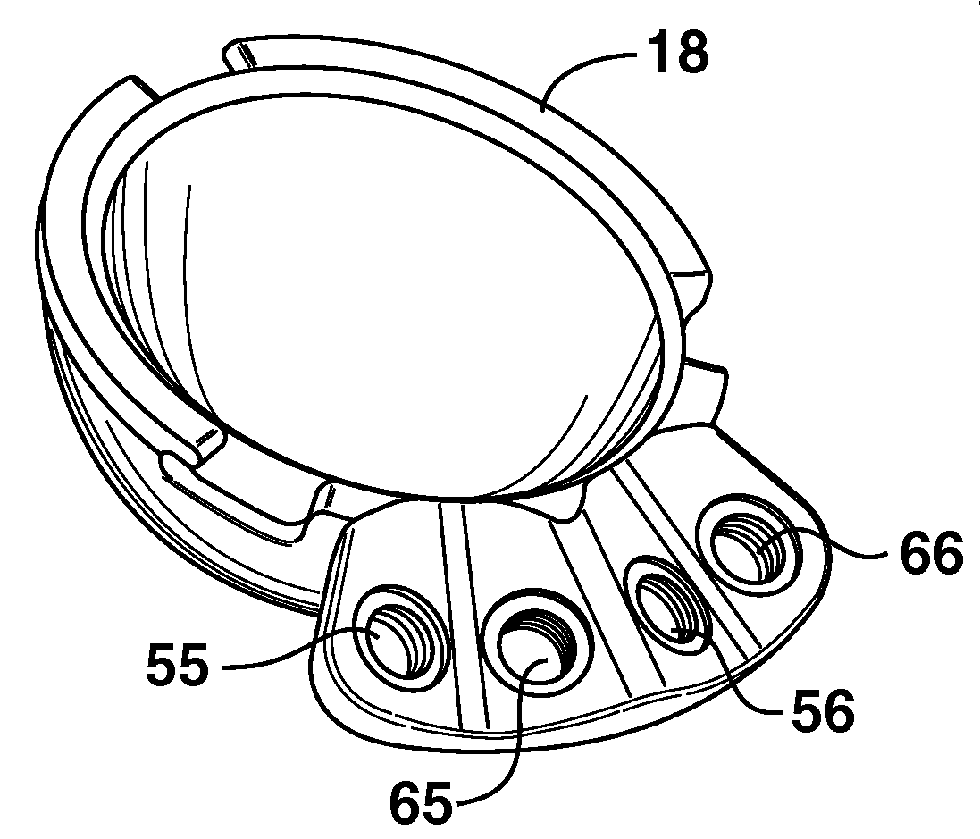
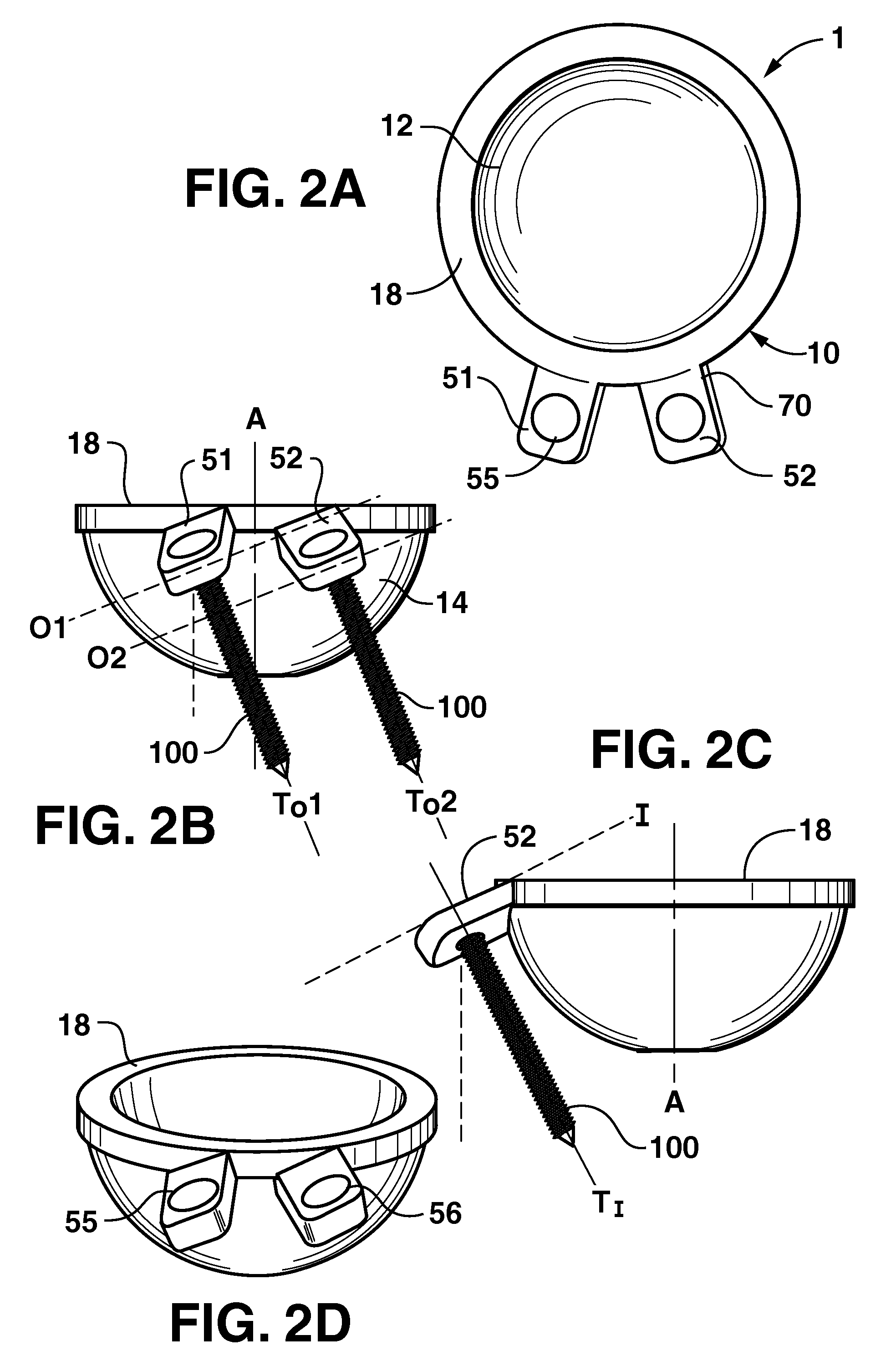
[0049]As shown in FIG. 2, the invention is a unitary acetabular cup prosthesis 1 for use in a deficient acetabulum of a hip of a patient. The prosthesis 1 includes a cup portion 10. As shown in FIG. 2B, the cup portion 10 has a generally dome-shaped wall 10 having an axis A and an upper rim 18. As indicated in FIG. 2A, an inner bearing surface 12 of the wall 10 is configured to pivotally engage a femoral head of a femoral hip prosthesis, in a manner known to those of skill in the art. As indicated in FIG. 2B, an outer surface 14 of the dome 10 is sized and configured to reside at ...


PUM

PropertyMeasurementUnit
angleaaaaaaaaaa
angleaaaaaaaaaa
sizeaaaaaaaaaa

Abstract

A unitary acetabular cup prosthesis (1) for a deficient acetabulum of a hip bone having a cup portion (10) and a pair of adjacent screw retaining members (51, 52) extending from the cup. A second pair of screw retaining members are preferably provided, with the first and second pair of screw retaining members oriented such that the prosthesis can be used in either a left or a right acetabulum of the patient. The screw retaining members may be formed on a single flange. The screw retaining members are fixedly inclined and offset relative to the rim (18) of the cup. Each screw retaining member has a threaded hole (55, 56) inclined relative to the rim such that an axis of the threaded hole converges toward the axis of the cup portion in one dimension and is oblique to the axis of the cup potion in a second dimension.A prosthesis for a deficient acetabulum of a patient having a cup portion and a flange member. The flange member has a base portion that extends upward along a portion of the upper rim. A generally planar screw retaining portion extends from the base portion, and is inclined from the base portion such that at least a lateral portion of a lower surface of the screw retaining portion is positioned below the upper rim while an upper surface of the screw retaining portion is positioned above the upper rim. The screw retaining portion has a first threaded hole, a second threaded hole and a neutral threaded hole, with the neutral hole positioned between the first and the second holes. The holes are inclined at certain orientations to allow for fixation with screws in a deficient acetabulum, and for use in a left or right hip.

Description

CROSS REFERENCE TO RELATED APPLICATIONS[0001]This application claims priority to U.S. patent application Ser. No. 10 / 941,210 (published as 2006 / 0058887A1), filed Sep. 15, 2004, which is pending, and to PCT / US / 32788 (published as WO 2006 / 31911), filed Sep. 14, 2005, which is pending.TECHNICAL FIELD[0002]The present invention relates to orthopedic prosthetic implants, and more particularly to an acetabular cup prosthesis that is configured particularly for treatment of deficient acetabula, such as the type encountered in hip dysplasia or osteoarthritis.BACKGROUND ART[0003]Conventional acetabular cup prostheses employ a two-part construction comprising a cup portion and a separate bearing insert. The cup is secured in the acetabulum by one or more screws, which pass through the wall of the cup and directly into the bone of the acetabulum. Once the cup is secured, the bearing insert is installed in the cup. To prevent shifting or loosening of the cup, the acetabulum is reamed prior to c...

Claims


Application Information

Patent Timeline
Patent Type & Authority Applications(United States)
IPC IPC(8): A61F2/32
CPCA61B17/1746A61F2310/00976A61F2/30767A61F2/34A61F2002/30578A61F2002/30685A61F2002/30774A61F2002/30785A61F2002/30787A61F2002/343A61F2002/3432A61F2310/00023A61F2310/00029A61F2310/00796A61B17/8057
Inventor DESMET, KOENSEYER, STEVEN F.SVARCZKOPF, ANTHONY J.
Owner MICROPORT ORTHOPEDICS HLDG INC
Why Eureka
Try Eureka