Method And Device For Cooling A Layer of Bulk Material On a Conveyor Grate

Active Publication Date: 2008-10-30
VON WEDEL +1
View PDF26 Cites 19 Cited by
  • Summary
  • Abstract
  • Description
  • Claims
  • Application Information

AI Technical Summary

Benefits of technology

[0011]The object of the invention is to provide a conveyor grate of the type stated in the preamble of Claim 1, having a simple design and which may be easily manufactured and installed, and which allows the moving gap and thus also the planks to have a narro

Problems solved by technology

A special design problem is posed by the moving gaps between the planks moved relative to one another, which must be designed in such a way that they prevent material from falling through.
A disadvantage of the known design is that the moving gaps are relatively wide due to the labyrinth structures provided therein, thus forming bulk material pathways which are not ventilated through the labyrinth structures and do not take part in the transport process, thereby impairing the transport efficiency of the conveyor grate.
A further disadvantage of the known conveyor grate is that the drive power required is increased considerably as the result of the friction between the bulk material falling into the moving gaps and the surfaces of the labyrinths.
In practice, the above-described

Method used


Image

  • Method And Device For Cooling A Layer of Bulk Material On a Conveyor Grate
  • Method And Device For Cooling A Layer of Bulk Material On a Conveyor Grate
  • Method And Device For Cooling A Layer of Bulk Material On a Conveyor Grate

Examples


Example

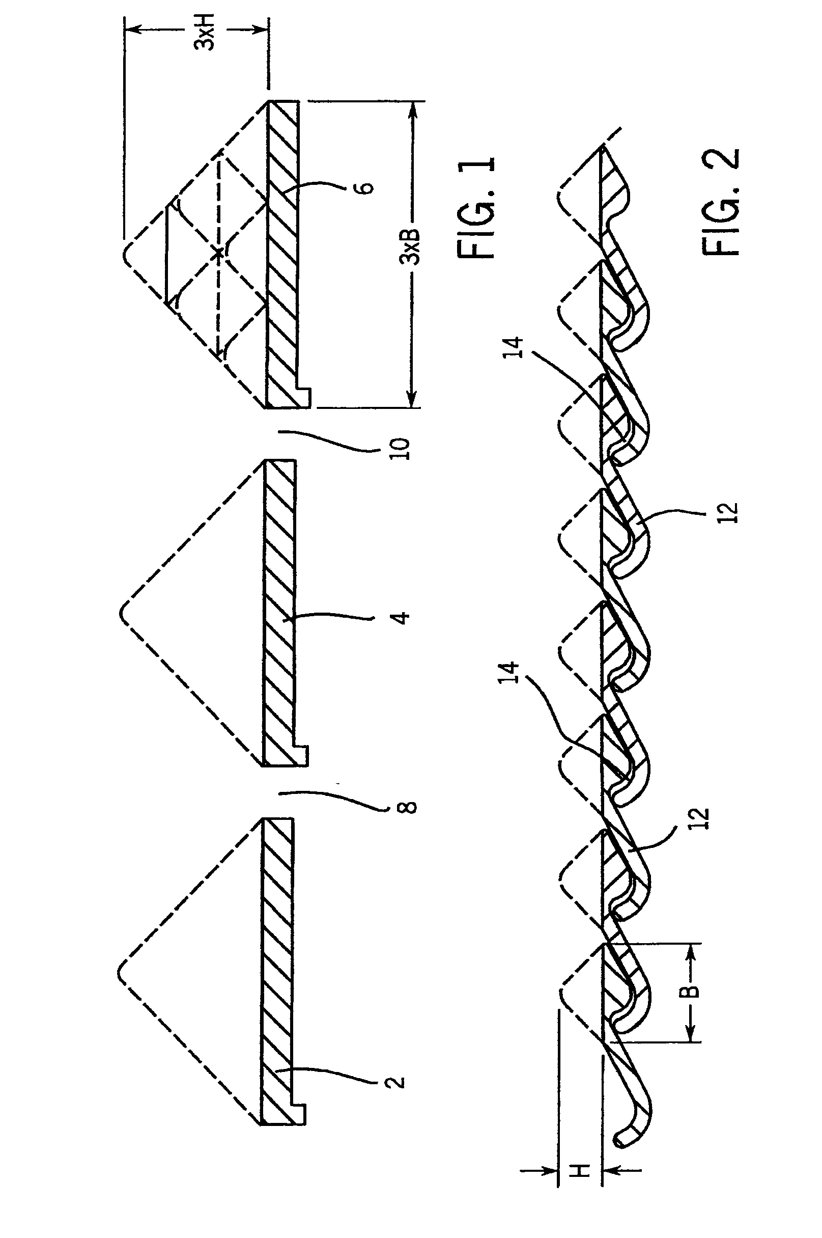
[0039]FIG. 1 schematically shows three adjacently positioned planks 2, 4, 6 of a conventional conveyor grate with moving gaps 8, 10 situated therebetween. The moving gaps 8, 10 have a relatively wide design to accommodate the labyrinth structures, not illustrated in the figure for improved clarity, which prevent bulk material from falling into a chamber located beneath the planks 2, 4, 6. As described above, the moving gaps 8, 10 become filled with bulk material. The area above the moving gaps 8, 10 does not take part in the ventilation. To achieve a specified desired ratio of the surface area of the planks taking part in the ventilation to the surface area of the moving gaps not taking part in the ventilation, the planks 2, 4, 6 must have a relatively wide design. As previously described, an open grate surface area of, for example, 2.5% of the total grate surface area is sought, whereby in the conventional grate illustrated in FIG. 1 the blow openings must be distributed on the pla...


PUM


Abstract

A conveyor grate for the transport and cooling of bulk material, for example cement clinker, comprises a grate floor having multiple planks (12), adjacently situated transverse to the direction of transport on associated support structures and operationally moved longitudinally relative to one another individually or in groups, with moving gaps (14) designed as blow openings situated therebetween, and a method for operating such a conveyor grate. The mutually facing side edges or side edge regions of two adjacent planks (12) form two complementary, mutually engaging profiles between which the moving gap (14) is formed. In the method according to the invention, at least a quantity of the cooling air is blown through the moving gaps (14) which is sufficient to blow the moving gaps (14) completely open.

Description

CROSS REFERENCES TO RELATED APPLICATIONS[0001]This application claims priority to German Patent Application No. 10 2007 019 530.5-24 filed on Apr. 25, 2007, which is fully incorporated herein.STATEMENT REGARDING FEDERALLY SPONSORED RESEARCH[0002]Not Applicable[0003]1. Technical Field[0004]The invention relates to a method and a device for cooling a layer of bulk material resting on a conveyor grate by means of cooling air blown through the grate floor, the grate floor being formed by multiple planks adjacently positioned transverse to the direction of transport and longitudinally moved relative to one another, with moving gaps situated therebetween which allow cooling air to pass through.[0005]2. Description of the Background Art[0006]Conveyor grates of the type described above have been implemented in various designs. The planks with the bulk material resting thereon are moved back and forth, individually or as a group, according to a specified motion pattern in such a way that a n...

Claims


Application Information

Patent Timeline
IPC IPC(8): F26B19/00F27D15/02
CPCB65G25/065F26B17/26F27D15/0213
Inventor VON WEDEL, KARL
Owner VON WEDEL
Why Eureka
Try Eureka