Wood cutting saw chain and replaceable cutting members

Inactive Publication Date: 2008-10-30
INDIGO INNOVATORS
View PDF21 Cites 4 Cited by
  • Summary
  • Abstract
  • Description
  • Claims
  • Application Information

AI Technical Summary

Benefits of technology

[0017]An advantage of designing the cutting member of sintered and compacted particulate material is that the material may advantageously be formed in near final net shape and used as processed with little machining except for grinding of the cutting edge. This enables the uniquely close tolerance of the tapers to produce a self-locking engagement of the cutting member and the base member. In use, the sintered material cutting member is placed near the seat surface and slid onto it in a direction opposite to the direction of chain travel. The self locking tapers of the cutting member and holder provide effective and strong self-locking connection between the cutting member and holder. Once in the locked position, the cutting member can only be removed by tapping it from the rear or using a specialized tool that applies force in the direction of chain travel. This provides for safe and effective installation and removal (i.e., quick change) of the cutting members on the holders. Because the self-locking taper is quick and effective in securing the cutting member to the holder, other fasteners are not necessary in the inventive design. The sintered and compacted material has much better hardness and durability compared to steel teeth, which may dramatically extend chain life compared to steel teeth and is believed to surpass previously attempted chain insert designs in quality and economics of manufacture. Fabrication of the cutting members is ex

Problems solved by technology

In many cases the chain and teeth of one saw have a design that cannot be used in a saw for a different application.
Also, chain tooth materials necessary for one application such as masonry, are not well suited to other applications such as wood cutting.
However, when cutting trees in an area where there are nails, staples or other metal articles that may have been inserted into the trees such as in areas near old farmland, saw chain employs more costly carbide-brazed steel cutting teeth because they c

Method used


Image

  • Wood cutting saw chain and replaceable cutting members
  • Wood cutting saw chain and replaceable cutting members
  • Wood cutting saw chain and replaceable cutting members

Examples


Embodiment Construction

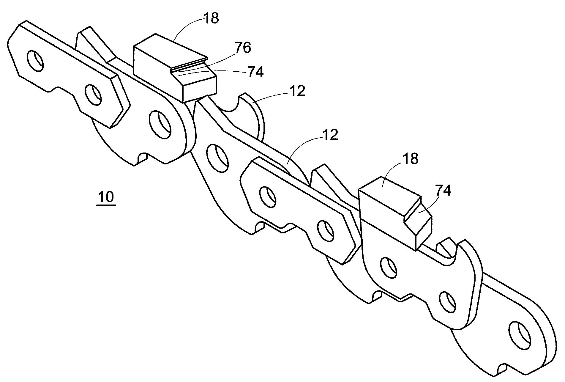
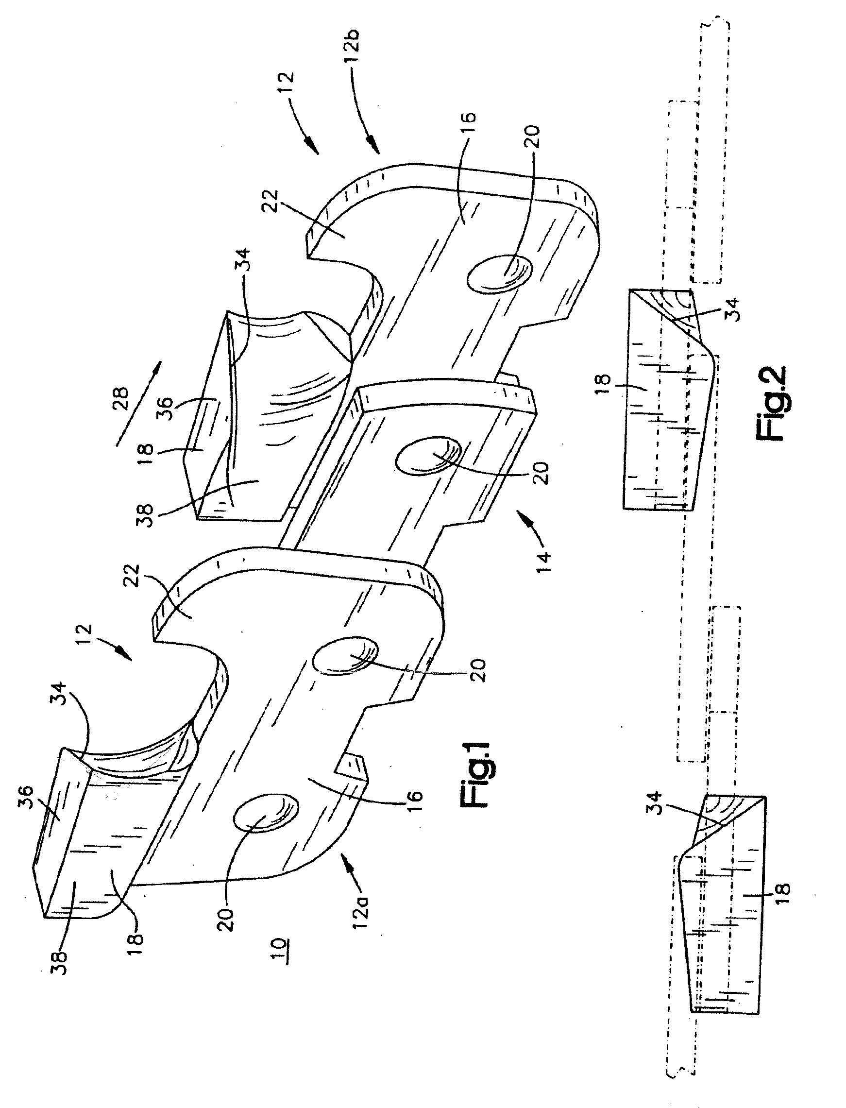
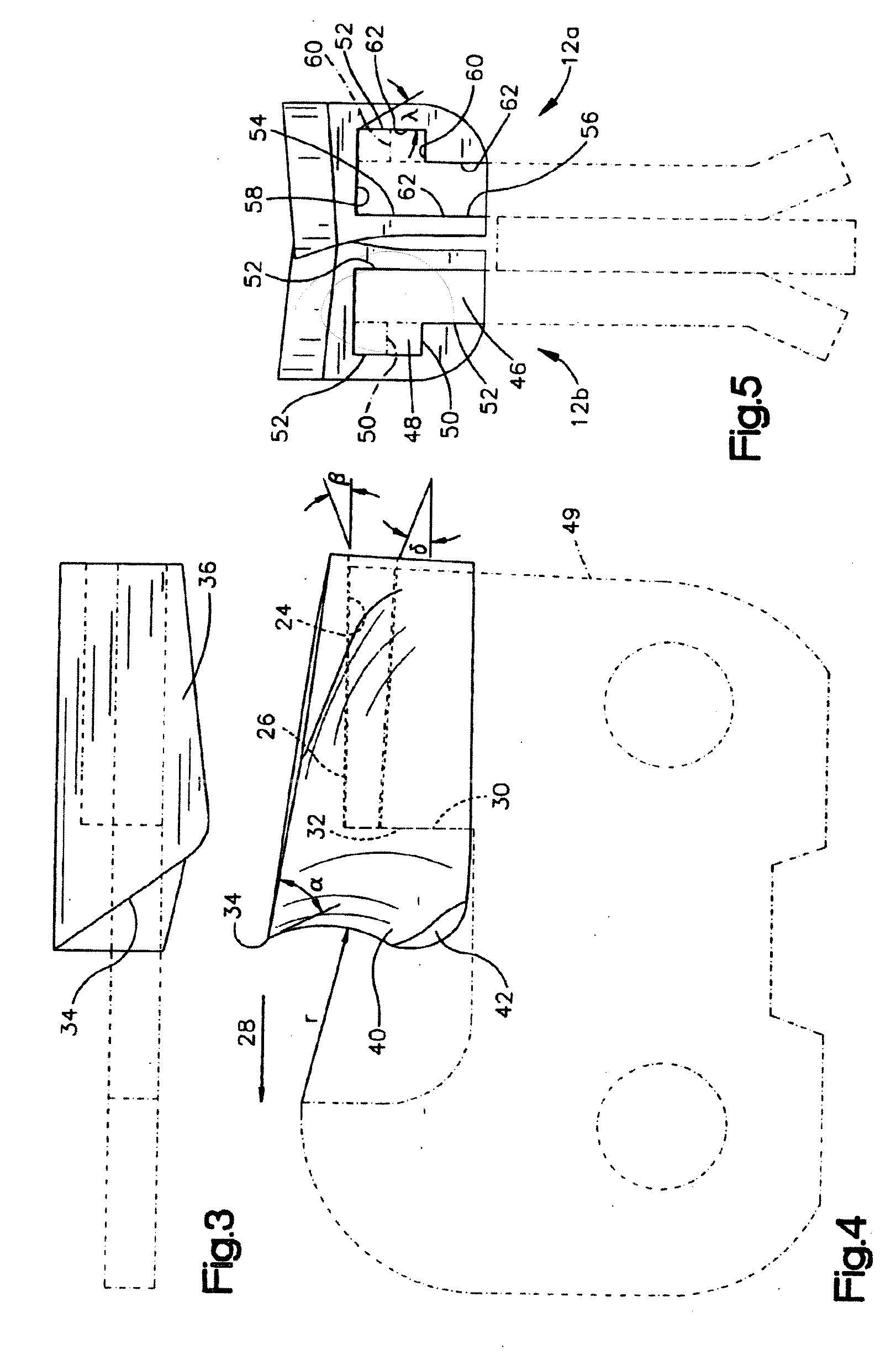
[0031]Turning now to the drawings, the inventive saw chain portion 10 includes a plurality of links including cutting links 12 and connecting links or tie-straps 14 located between cutting links, which pivotally connect the cutting links and drive links (not shown) together in a well known manner. The cutting links or cutters 12 each comprise a holder or base member 16 pivotally connected at each end to the connecting links and quick change cutting members 18 connected to the holders. The cutting links are designed so as to alternate right and left handed with regard to the cutting edge (12a, 12b, respectively, in FIGS. 1 and 5) such that they are a mirror image of one another relative to a plane in which the connecting links reside. Rivets 20 pivotally fasten the saw chain links together in a well known manner. The function of the cutters and the purpose of their design is to cut wood fibers. Those skilled in the art will appreciate in view of this disclosure that a complete saw ch...


PUM

PropertyMeasurementUnit
Angleaaaaaaaaaa
Angleaaaaaaaaaa

Abstract

A quick change cutting link of a saw chain for cutting wood comprises a base member adapted to be pivotally connected to other links of the saw chain. The base member comprises a seat surface. A cutting member comprising a “V” notch releasably engages the seat surface of the base member. Attached to the “V” notch is a carbide tip, including a cutting edge. The carbide tip is accurately placed in the “V” notch by mating with a small piece of metal in the “V” notch. The carbide tip is then sinterbrased to the cutting member. The cutting member and seat surface may also comprise an inverted L-shaped protrusion and the other includes an inverted L-shaped recess for receiving the inverted L-shaped protrusion. The inverted L-shaped protrusion and recess may be designed so as to form a wedge.

Description

[0001]This application is a continuation-in-part of U.S. patent application Ser. No. 10 / 730,323 entitled “Wood Cutting Saw Chain And Replaceable Cutting Members,” filed on Feb. 17, 2004, the disclosure of which is herein incorporated herein by reference.[0002]The present invention is directed to a chain for cutting wood such as chain saws and timber harvesters.BACKGROUND OF THE INVENTION[0003]There are a variety of cutting devices in numerous applications including masonry, machining, metal cutting, glass cutting, wood cuffing and stone cutting, which can employ a chain, rotary blade or other cutting element. Saw chains employ a chain design and material components unique to the particular application. In many cases the chain and teeth of one saw have a design that cannot be used in a saw for a different application. Also, chain tooth materials necessary for one application such as masonry, are not well suited to other applications such as wood cutting.[0004]In the timber industry, ...

Claims


Application Information

Patent Timeline
IPC IPC(8): B27B33/14
CPCB27B33/144Y10T83/925Y10T83/9329Y10T83/909Y10T83/913
Inventor SZYMANSKI, DAVID
Owner INDIGO INNOVATORS
Why Eureka
Try Eureka