

Clip-style hearing protector
- Summary
- Abstract
- Description
- Claims
- Application Information
AI Technical Summary
Benefits of technology
Problems solved by technology
Method used
Image

Examples
third embodiment
[0031]Reference will now be made in detail to embodiments of the invention, one or more examples of which are illustrated in the drawings. Each example is provided by way of explanation of the invention, and not meant as a limitation of the invention. For example, features illustrated or described as part of one embodiment can be used with another embodiment to yield still a It is intended that the present invention include these and other modifications and variations.
first embodiment
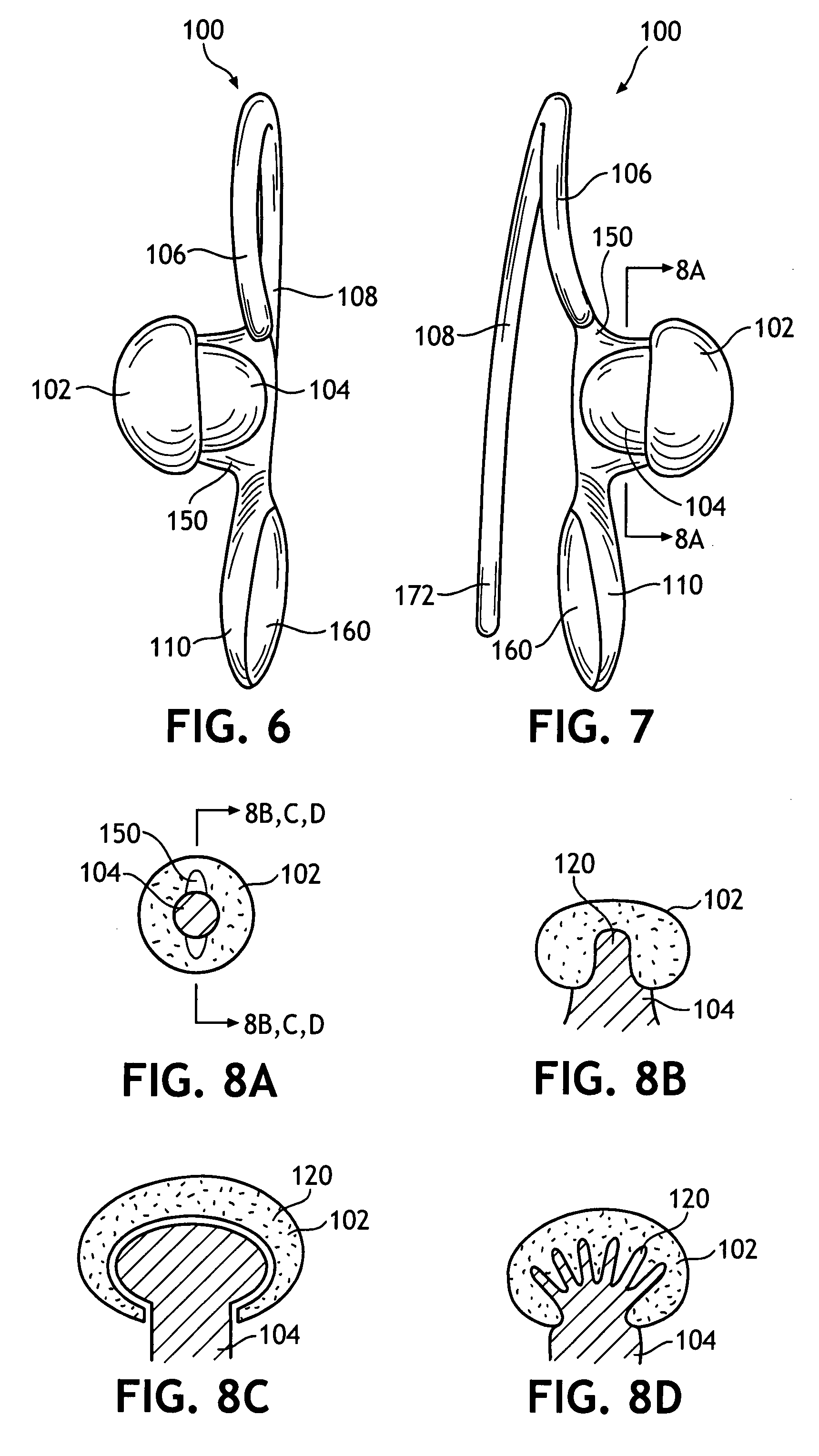
[0032]As shown in FIGS. 6-7, hearing protector 100 desirably has a unitary construction, with the possible exception of the plug 102. The neck 104, shoulder 106, handle 110, and arm 108 may be molded from a plastic material having the following characteristics: flexible enough to move the arm 108 to the backside of pinna 12 as neck 104 is positioned near the concha 26; durable enough to be used more than one time; moldable, as by injection molding or the like; and steady-state in that it does not exhibit significant loss of stiffness under a continuous load, allowing neck 104 and plug 102 to maintain an effective force toward the ear canal 26. Desirably, a material such as polyethylene is used. However, it is contemplated that the ear clip portion of hearing protector 100 may be manufactured from nylon, plastics such as polypropylene, polyvinyl chloride, polycarbonate; metals such as titanium, steel, or aluminum composites; or elastomer such as silicon, thermoplastic elastomer (TPE)...
PUM
 Abstract
Description
Claims
Application Information