Depth Correlation Device for Fiber Optic Line

a fiber optic line and depth correlation technology, applied in the field of fiber optic cables, can solve the problems of slack being built into, confusion, and disassociation between

Active Publication Date: 2008-10-30
BAKER HUGHES INC
View PDF18 Cites 32 Cited by
  • Summary
  • Abstract
  • Description
  • Claims
  • Application Information

AI Technical Summary

Benefits of technology

[0008]A correlation system is provided to allow association of readings from a cable that is supported by a string but that is coiled around or has slack in one or many locations to a specific location along the string itself. Heat sources can be placed along the string to periodically or continuously give off heat that can be detected by a cable su

Problems solved by technology

The problem is that to accommodate the various equipment on the string as well as to facilitate assembly of the string and associated equipment, requires that slack be built into the fiber optic cable.
The problem is that the provision of slack at one or multiple locations along the length of the cable creates a disassociation between the position along the length of the cable and the physical location of that portion of the cable with respect to the running length of tubular into the well.
As a result, it becomes unclear as to where in the well the temperature profile transmitted through the cable is actually located in the well.
Additionally, an optical fiber cable within a line can have a variable length, which can occur as a result in variability of the overstuffing used when installing the fiber optic cable into the li

Method used


Image

  • Depth Correlation Device for Fiber Optic Line
  • Depth Correlation Device for Fiber Optic Line

Examples


Embodiment Construction

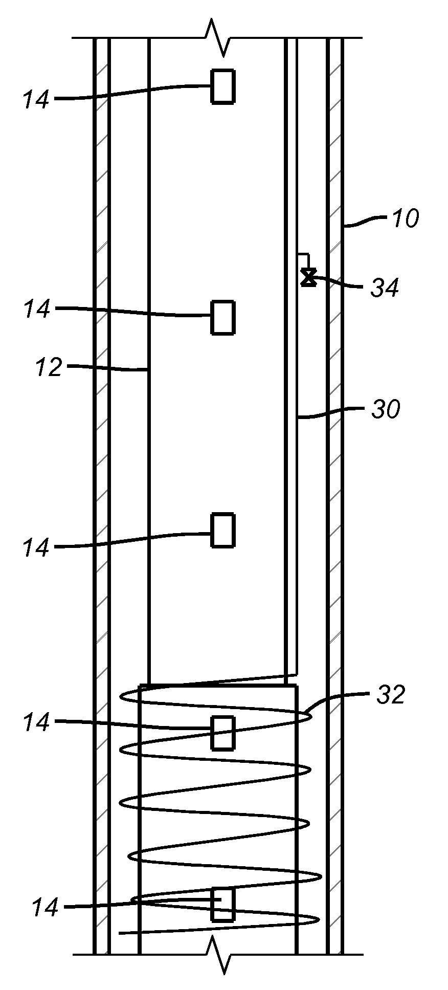
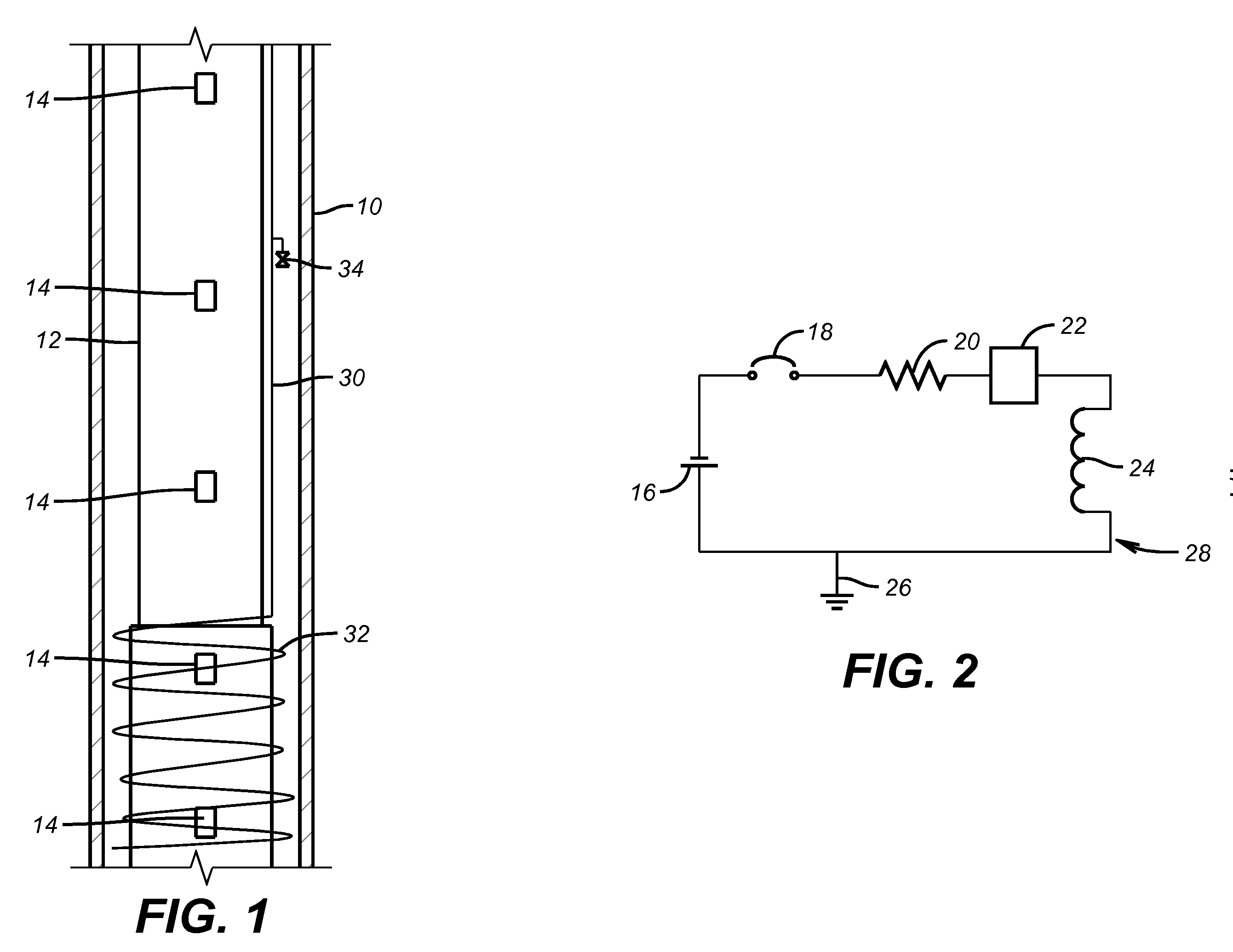
[0011]FIG. 1 shows casing 10 surrounding tubing string 12 in a wellbore. Alternatively, open hole applications are within the scope of the invention. Mounted to the string 12 are devices 14 that in the preferred embodiment emit heat. While the devices 14 are shown to be identical in the preferred embodiment, they don't all need to be the same nor do they all need to operate on the same principle. In the preferred embodiment the devices 14 are heat generators that can be self contained, as illustrated in more detail in FIG. 2. The circuit includes a power supply 16 a switch 18, a resistor 20, a thermostat 22 and a heating coil 24. Alternatively, power can come from outside the interval where the devices 14 are located, such as from the surface such as by an adjacent line. The circuit can include a ground 26 to the string 12. The switch 18 can be actuated on and off in a number of ways from the surface or locally from a cycle timer that can be made part of the circuit 28.

[0012]A line ...


PUM


Abstract

A correlation system is provided to allow association of readings from a cable that is supported by a string but that is coiled around or has slack in one or many locations to a specific location along the string itself. Heat sources can be placed along the string to periodically or continuously give off heat that can be detected by a cable such as a fiber optic. The location of the sources along the string is known and the location along the cable is determined from the location on the cable where the heat generated by the source is sensed. One or more sources can be used and correlation can be by periodic sampling or in real time. The sources may by powered locally or from the surface.

Description

FIELD OF THE INVENTION[0001]The field of the invention is the use of fiber optic cable to measure downhole conditions and more particularly a device that correlates a length along the cable to an associated well location.BACKGROUND OF THE INVENTION[0002]Temperature distribution downhole can be part of the data that a well operator needs to monitor downhole conditions. One way this information has been obtained in the past is through a fiber optic cable that extends from the surface to the downhole completion(s) and gives data at the surface of the sensed temperature at any point along the fiber optic cable. The problem is that to accommodate the various equipment on the string as well as to facilitate assembly of the string and associated equipment, requires that slack be built into the fiber optic cable. Generally, this slack is provided by adding coils around portions of the string. The slack that is provided allows running in with minimal damage to the cable and facilitates assem...

Claims


Application Information

Patent Timeline
IPC IPC(8): E21B47/12
CPCE21B47/04E21B47/123E21B47/09E21B47/065E21B47/07E21B47/135
Inventor MENDEZ, LUIS E.POLAND, STEPHEN H.
Owner BAKER HUGHES INC
Why Eureka
Try Eureka