Integrated multispar torsion box of composite material

a composite material and multi-spar technology, applied in the direction of other domestic objects, transportation and packaging, fuselages, etc., can solve the problems of increased logistic capacity, weight penalties, high production and assembly costs, etc., and achieve the effect of less parts, less weight, and greater manufacturing cost saving

Active Publication Date: 2008-10-30
AIRBUS OPERATIONS SL
View PDF7 Cites 34 Cited by
  • Summary
  • Abstract
  • Description
  • Claims
  • Application Information

AI Technical Summary

Benefits of technology

[0017]The previous torsion box is created starting from individual elements in composite material which are already integrated from the stacking and which in turn assume several structural functions (they form part of the stringer, spar and / or skin at the same time), achieving a required complete integrated structure upon joining several of these elements before the final co-curing phase. This involves having all the advantages of an integrated structure, in addition to a greater manufacturing cost saving as there are less parts to be stacked and a more uniform passage of loads between the stacked elements.

Problems solved by technology

This involves different assembly stations and a large amount of joining elements, which entails weight penalties, high production and assembly costs, greater necessary logistic capacity and worse aerodynamic quality in outer surfaces.
At this point, the composite material requires a rather expensive curing process to achieve all its properties.
The problem consists mainly of generating sufficient pressure in all the elements during the joint curing process.
However, all these solutions start from the basis of individually “pre-stacking” the basic structural elements and curing them jointly with the suitable jigs, which is not a real complete integration, while at the same time the manufacturing costs are high due to the high number of parts to be stacked, there further being a non-uniform passage of loads between the stacked elements.

Method used


Image

  • Integrated multispar torsion box of composite material
  • Integrated multispar torsion box of composite material
  • Integrated multispar torsion box of composite material

Examples


Embodiment Construction

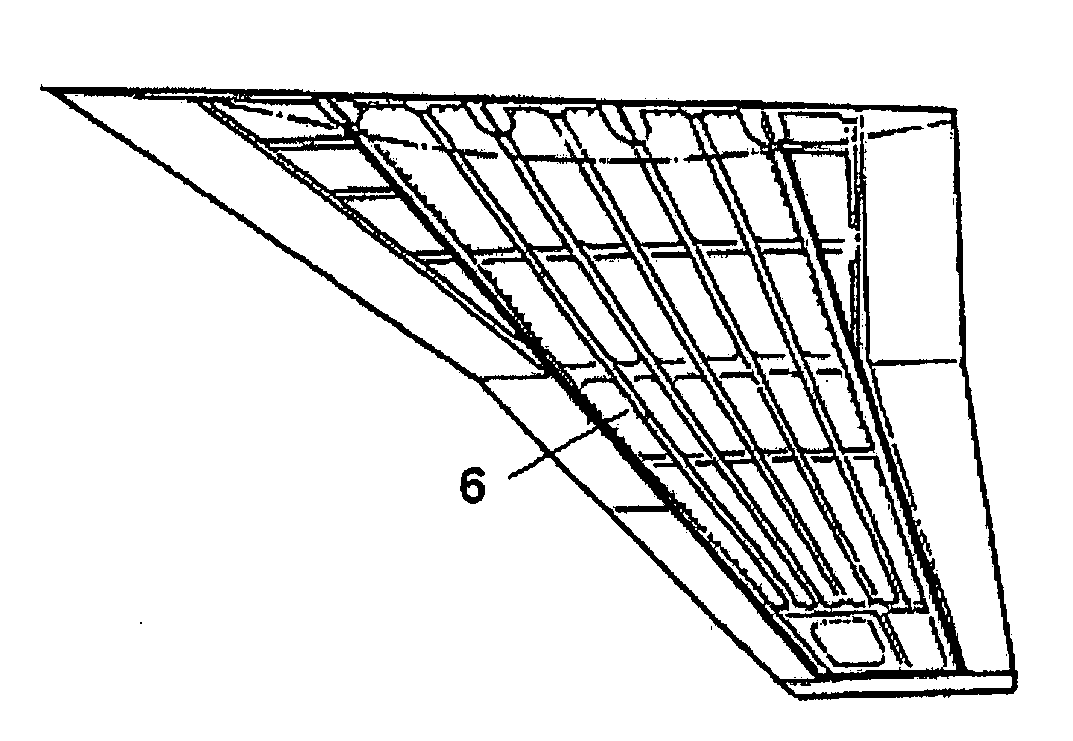
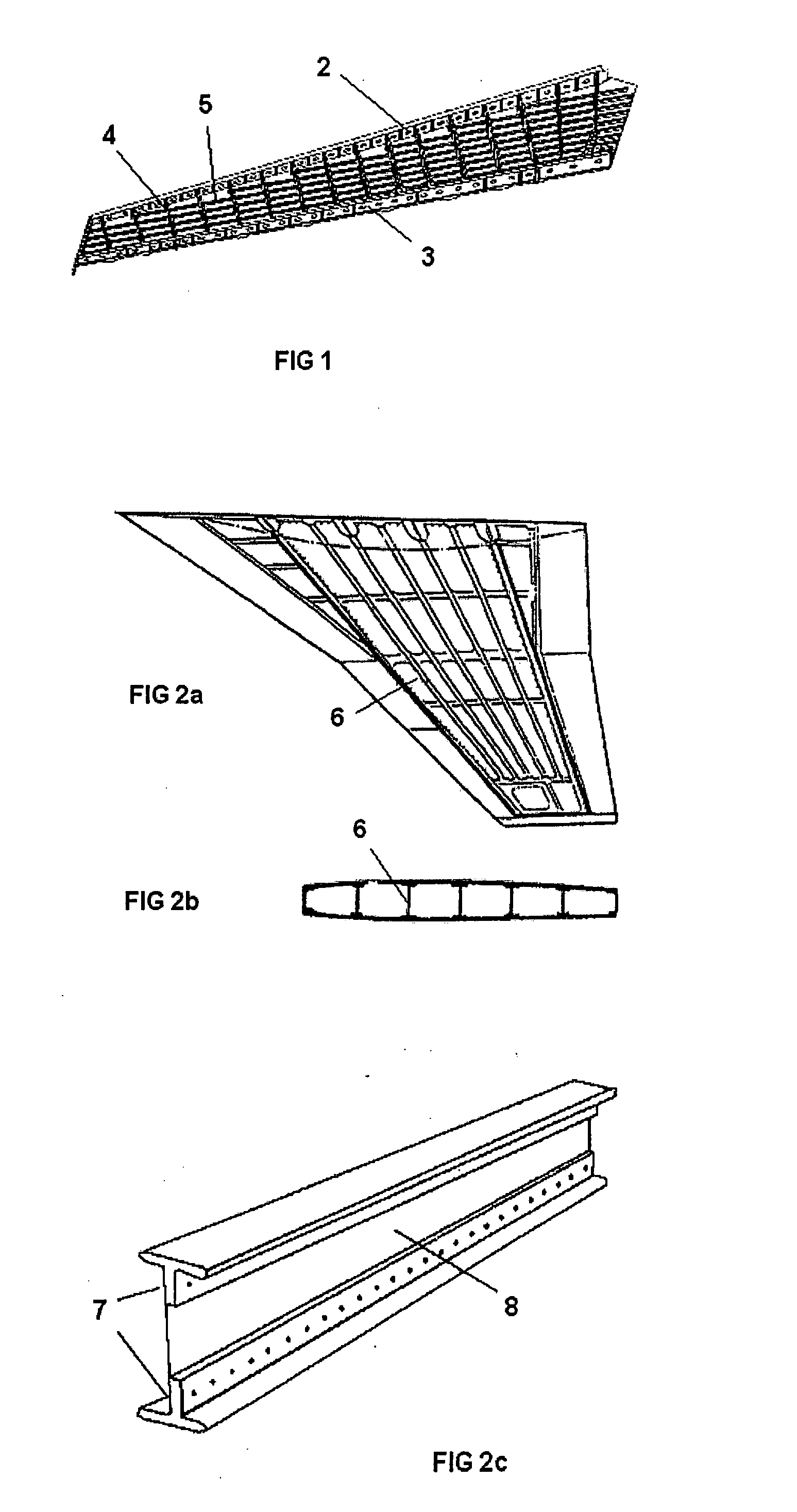
[0039]The invention relates to an integrated multispar torsion box structure of composite materials with longitudinal stiffeners with a T-shaped o I-shaped cross-section, all of this being co-cured. The composite material can be both carbon fiber and fiberglass with thermosetting or thermoplastic resin. The main field of application is aeronautical structures with supporting surfaces, although they can also be applied to other structures with similar features.

[0040]An integrated structure is one in which the different structural elements subjected to different stresses (shearing stress, normal stress etc.) are manufactured at one time or start from a single part. This is another advantage of the use of composite materials because, due to their conditions of independent layers which can be stacked in the desired manner, they offer the possibility of further integrating the structure, which further causes a cost saving since there are less individual parts to be assembled.

[0041]The ma...


PUM

PropertyMeasurementUnit
torsional rigidityaaaaaaaaaa
rigidityaaaaaaaaaa
pressureaaaaaaaaaa

Abstract

The invention relates to an integrated multispar torsion box structure of composite material for aircraft, comprising a lower skin (12), an upper skin (11), several spars (9), each of which comprises in turn a chord (13) and a web (14), several stringers (10) in the lower skin (12) and several stringers (10) in the upper skin (11), characterized in that the mentioned integrated torsion box structure is achieved by means of joining unitary U-shaped structural elements (15), unitary U-shaped structural elements (16) with a flap and unitary C-shaped structural elements (17) with a flap. The invention also relates to a method for manufacturing an integrated multispar torsion box structure of composite material for aircraft.

Description

FIELD OF THE INVENTION [0001]The present invention relates to an integrated multispar torsion box structure of composite material as well as to a method for manufacturing such structure.BACKGROUND OF THE INVENTION [0002]It is commonly known that the aeronautical industry requires structures which on one hand can support the loads to which they are subjected, complying with high strength and rigidity requirements, and on the other hand are as light as possible. A result of this requirement is the increasingly extended use of composite materials in primary aircraft structures, involving an important weight saving compared to the use of metallic materials.[0003]The main structure for supporting surfaces of airplanes is formed by a leading edge, a torsion box and a trailing edge. The torsion box of an aircraft is in turn formed by several structural elements. Typically, the process for manufacturing a torsion box is considerably manual and is carried out in a number of steps. The struct...

Claims


Application Information

Patent Timeline
Patent Type & Authority Applications(United States)
IPC IPC(8): B64C1/06B29C65/02
CPCB29C70/342B29D99/0014B29L2031/3085Y10T156/1002B64C3/185Y02T50/433B64C1/065B29C70/34Y02T50/40
Inventor MUNOZ LOPEZ, MARIA PILARCRUZ DOMINGUEZ, FRANCISCO JOSECANO CEDIEL, JOSE DAVID
Owner AIRBUS OPERATIONS SL
Why Eureka
Try Eureka