Stackable mat construction

a technology of stackable mats and mats, which is applied in the direction of single unit paving, applications, roads, etc., can solve the problems of not being able to move the mat, the mat may be difficult to retrieve from the bottom, and the mat may end up being left and never retrieved, etc., and achieves the effect of fast assembly

Active Publication Date: 2018-03-13
QUALITY MAT
View PDF78 Cites 6 Cited by
  • Summary
  • Abstract
  • Description
  • Claims
  • Application Information

AI Technical Summary

Benefits of technology

[0006]The foregoing needs are met, to a great extent, by the present invention, wherein in one aspect an apparatus is provided that in some embodiments it is desirable to provide a stackable mat that is stable in deep water by allowing for water flow-through, can easily be retrieved from water areas and requires fewer stacked mats, thus creating faster assembly, and is heavy enough to stay in position when placed.
[0013]Advantageously, the stacker mat further comprises lifting elements including D-shaped rings, O-shaped rings, chains or cables that are connected directly to the stacker mat to allow overhead lifting of the stacker mat, wherein the lifting elements are optionally coated, painted or treated to provide additional water and environmental resistance.
[0015]For all embodiments, it is preferred to have the internal support structure made of environmentally resistant materials or otherwise treated or configured to avoid deterioration of the internal support structure when repeatedly exposed to water. For example, the truss or elongated members can be made of metal or plastic materials or by treated, coated or painted wood. Also, the metal components can be painted or coated if desired, e.g. painting or galvanizing a steel plate to prevent rust from appearing.

Problems solved by technology

Conventional mats also have problems with the mats moving due to tidal surge or rising waters, for example.
Also, when it is time to remove these mats there may be challenges, such as, the mats may be hard to retrieve from the bottom being submerged in water.
A user may need to “fish” for the mats with heavy tools or equipment, such as a track hoe excavator which may damage the soil on the bottom.
Further, given these difficulties, the mats may end up being left and never retrieved which may not be desirable in environmentally sensitive areas.

Method used


Image

  • Stackable mat construction
  • Stackable mat construction
  • Stackable mat construction

Examples


Embodiment Construction

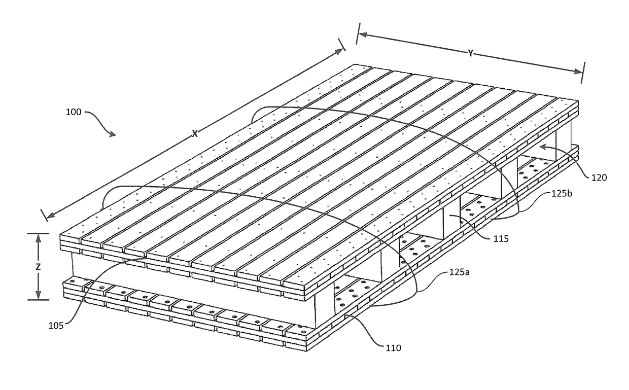
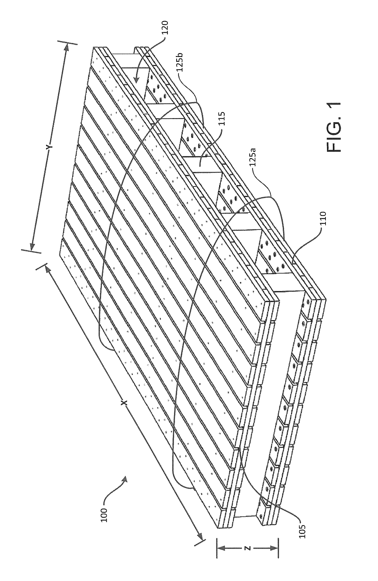
[0030]The invention will now be described with reference to the drawing figures, in which like reference numerals refer to like parts throughout. An embodiment in accordance with the present invention provides a stackable mat platform, support, or roadway used as filler in deep water or swampy areas lacking the same. The present invention may be configured to gain height by reducing weight and allowing water to flow in between each mat platform configuration. Further, the present invention may be configured to be more readily utilized and retrieved from the deep water or swampy areas thereby saving time and money for a user.

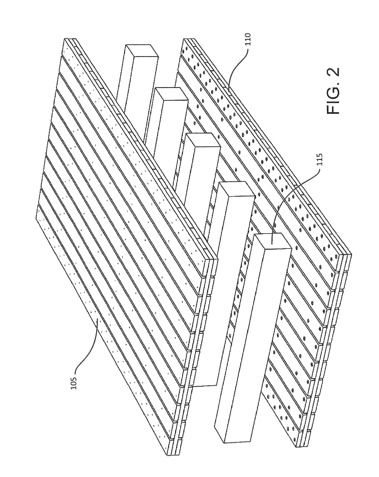
[0031]Generally, the invention will utilize two mats that are spaced apart by various support structures that act as internal spacers. The two mats can be any of those disclosed in U.S. application Ser. Nos. 15 / 056,212 and 15 / 056,344 each filed Feb. 29, 2016, the entire contents of which are expressly incorporated herein by reference thereto. Preferably, these ma...


PUM

PropertyMeasurementUnit
thicknessaaaaaaaaaa
thicknessaaaaaaaaaa
thicknessaaaaaaaaaa

Abstract

A stackable mat includes a first industrial mat, a second industrial mat and an internal support structure. The mats each have a plurality of layers or plies of construction materials for forming the upper and lower portions, respectively, of the stacker mat, and have a thickness that provide support for vehicle movement thereover. The internal support structure includes a truss or elongated members for retaining the first and second mats in parallel spaced relation at a distance that is greater than the thickness of the first industrial mat. Preferably, the internal support structure and the second industrial mat or both the first and second industrial mats are configured with sufficient openings to allow water to flow therethrough so that the stacker mat may be placed in wet areas to form a temporary roadway or platform.

Description

CROSS-REFERENCE TO RELATED APPLICATIONS[0001]This application is a continuation-in-part of U.S. application Ser. No. 15 / 081,340 filed Mar. 25, 2016, which is a continuation-in-part of U.S. application Ser. No. 15 / 056,212 filed Feb. 29, 2016, which in turn is a continuation-in-part of U.S. application Ser. No. 14 / 839,888 filed Aug. 28, 2015, now U.S. Pat. No. 9,315,949, which claims the benefit of U.S. provisional application Nos. 62 / 054,186 filed Sep. 23, 2014, 62 / 138,143 filed Mar. 25, 2015 and 61 / 158,196 filed May 7, 2015. This application also claims the benefit of U.S. provisional patent applications Nos. 62 / 211,662 filed Aug. 28, 2015 and 62 / 211,664 filed Aug. 28, 2015. The entire content of each foregoing application is expressly incorporated herein by reference thereto.FIELD OF THE INVENTION[0002]The present invention relates generally to a reusable system for the construction of roadways and equipment support surfaces in areas having poor ground integrity and natural or arti...

Claims


Application Information

Patent Timeline
Patent Type & Authority Patents(United States)
IPC IPC(8): E01C9/08B32B27/08B32B21/12E01C11/24E01C11/16E01C5/14E01C5/22B32B7/08B32B3/08B32B15/095B32B21/04B32B7/00B32B7/04B32B3/26B32B15/20B32B21/08B32B3/02B32B3/10B32B3/14B32B3/18B32B15/18
CPCE01C9/086B32B27/08E01C5/14E01C5/22E01C11/16E01C11/24B32B21/12B32B2607/00B32B3/02B32B3/085B32B3/10B32B3/14B32B3/18B32B3/26B32B7/005B32B7/045B32B7/08B32B15/095B32B15/18B32B15/20B32B21/042B32B21/045B32B21/08B32B2250/44B32B2255/06B32B2255/08B32B2255/205B32B2255/24B32B2272/00B32B2307/546B32B2307/548B32B2307/558B32B2307/56B32B2307/712B32B2307/726B32B2307/7265B32B2307/732B32B2471/00B32B7/03B32B7/05
Inventor PENLAND, JR., JOE
Owner QUALITY MAT
Why Eureka
Try Eureka