
Split Mold Insert Positioning Device and a Method of Use

a positioning device and mold insert technology, applied in the field of mold systems, can solve the problems of misalignment of the first neck ring half, the inability to easily form the neck region by using the cavity and core halves, etc., and achieve the effect of reducing operating costs and reducing neck ring wear

Inactive Publication Date: 2008-10-30
HUSKY INJECTION MOLDING SYST LTD
View PDF3 Cites 8 Cited by
  • Summary
  • Abstract
  • Description
  • Claims
  • Application Information

AI Technical Summary

Benefits of technology

[0015]A technical effect, amongst others, of the aspects of the present invention may include reduced neck ring wear, as well as the cavity and the cavity flange. Another technical effect of the aspects of the present invention may include decreased operating costs due to less frequent replacement of worn neck rings and / or cavity inserts. It should be expressly understood that not all of the technical effects, in their entirety, need be realized in each and every embodiments of the present invention.

Problems solved by technology

As is appreciated in the art, the neck region can not be easily formed by using the cavity and core halves.
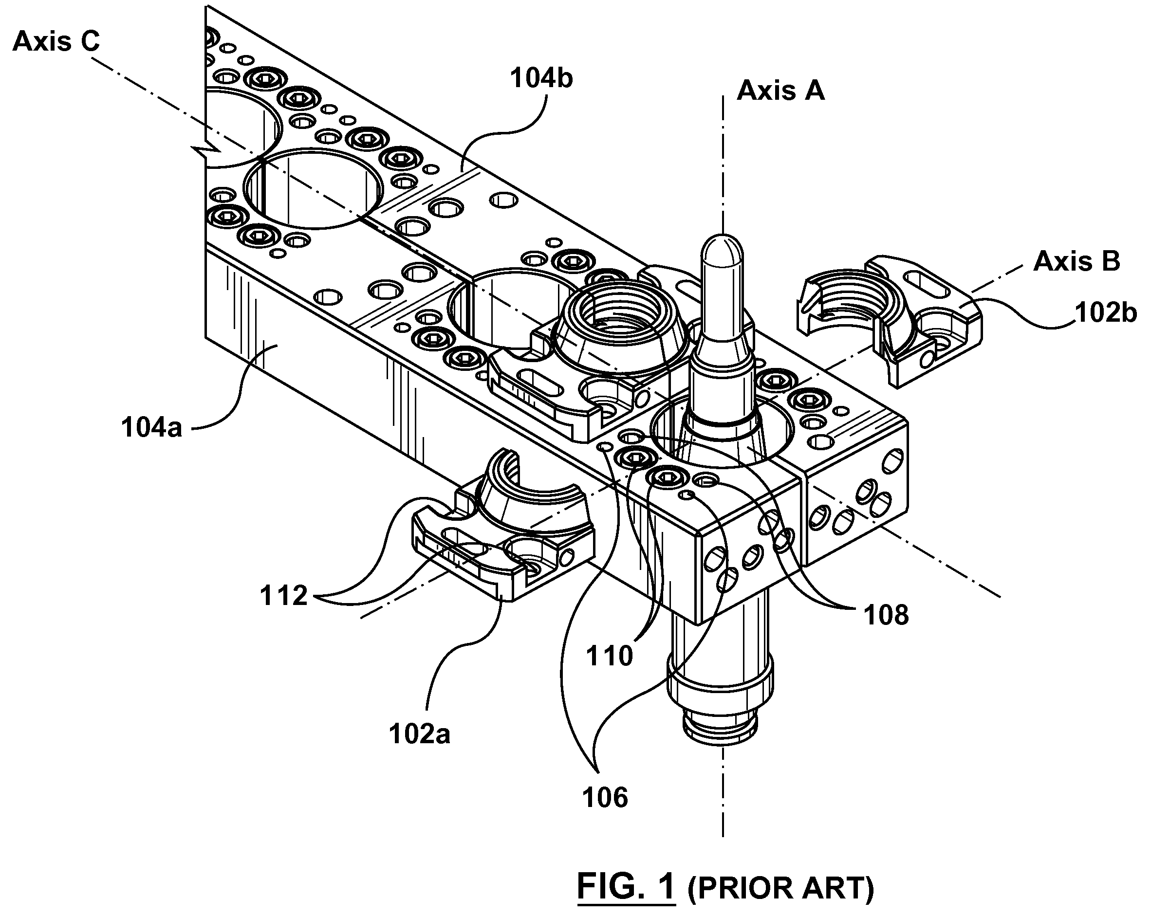
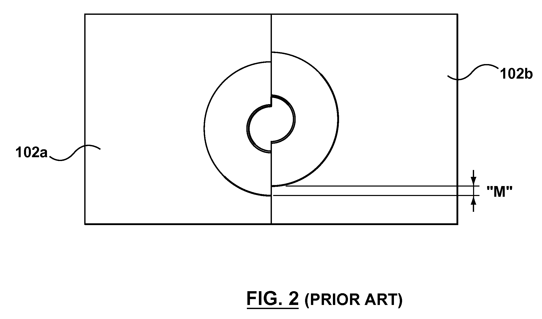
One of the main problems associated with the current procedure for mounting the neck ring pair 102 onto the first and second slides 104a, 104b is that it is susceptible to causing the first neck ring half 102a to be mis-aligned relative to the second neck ring half 102b.
Other types of mis-alignment may also happen within the prior art approaches.
As is very well known in the art, the first and second neck ring halves 102a, 102b are relatively expensive to manufacture and, as such, premature surface wear leads to increased costs.

Method used


Image

  • Split Mold Insert Positioning Device and a Method of Use
  • Split Mold Insert Positioning Device and a Method of Use
  • Split Mold Insert Positioning Device and a Method of Use

Examples


Embodiment Construction

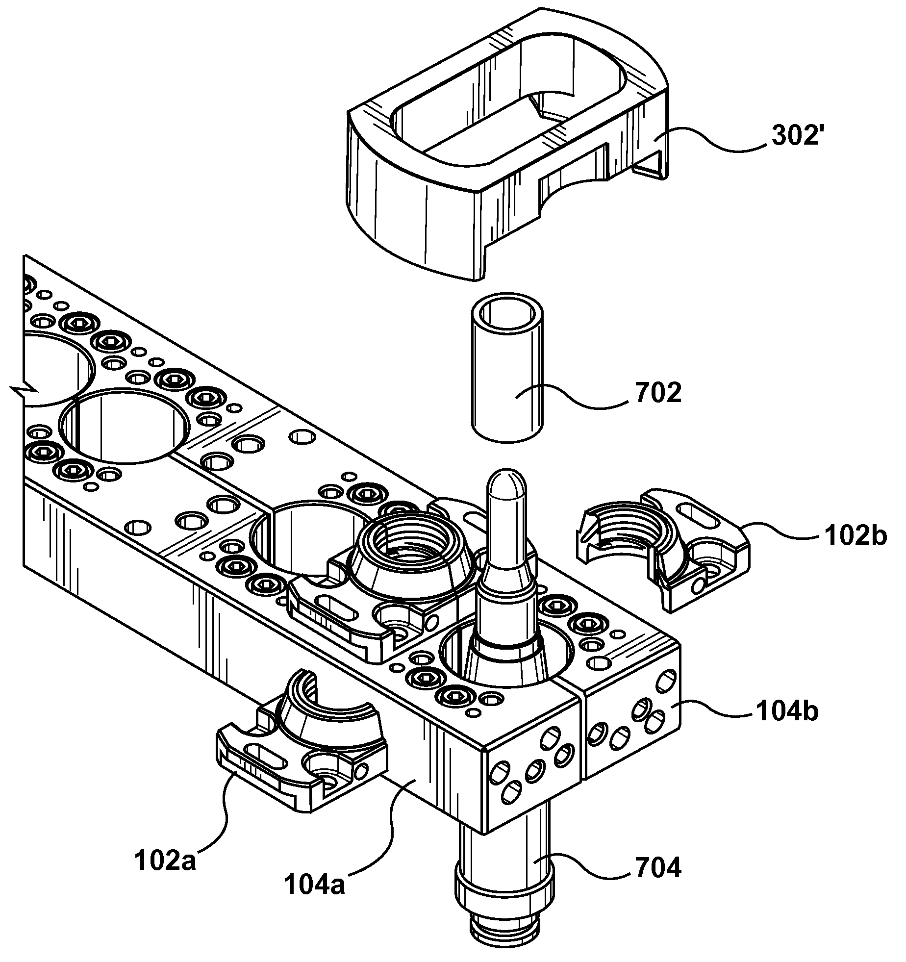
[0025]With reference to FIG. 3, FIG. 4 and FIG. 5, there is depicted a non-limiting embodiment of a positioning device 302 according to a non-limiting embodiment of the present invention. In some embodiments of the present invention, the positioning device 302 can be used to perform a method of aligning a split mold insert, such as for example, the first neck ring half 102a and the second neck ring half 102b of FIG. 1. The first neck ring half 102a and the second neck ring half 102b can be part of an injection molding system that is used for producing a preform capable of being blow-molded into a beverage container and the like. However, this need not be so in every embodiment of the present invention. It should be expressly understood that embodiments of the present invention can be used for aligning split mold inserts used in plastic molding systems, plastic compression systems, metal molding systems, glass molding systems, just to name a few examples. The positioning device 302 c...


PUM

PropertyMeasurementUnit
diameteraaaaaaaaaa
heightaaaaaaaaaa
flexibleaaaaaaaaaa

Abstract

According to the embodiments of the present invention, there is provided a split mold insert positioning device and a method of use thereof. More specifically, a split mold insert positioning device is provided. The split mold insert positioning device comprises a split mold insert positioning interface dimensioned in a complementary arrangement to a reference dimension of a given split mold insert; and a tooling interface for providing access to the given split mold insert when the split mold insert positioning interface is positioned over the given split mold insert.

Description

FIELD OF THE INVENTION[0001]The present invention generally relates to, but is not limited to, molding systems, and more specifically the present invention relates to, but is not limited to, a split mold insert positioning device and a method of use thereof.BACKGROUND OF THE INVENTION[0002]Molding is a process by virtue of which a molded article can be formed from molding material by using a molding system. Various molded articles can be formed by using the molding process, such as an injection molding process. One example of a molded article that can be formed, for example, from polyethelene terephalate (PET) material is a preform that is capable of being subsequently blown into a beverage container, such as, a bottle and the like.[0003]As an illustration, injection molding of PET material involves heating the PET material (ex. PET pellets, PEN powder, PLA, etc.) to a homogeneous molten state and injecting, under pressure, the so-melted PET material is injected into a molding cavit...

Claims


Application Information

Patent Timeline
Patent Type & Authority Applications(United States)
IPC IPC(8): B29C59/02
CPCB29C45/2606B29C45/33B29K2105/253
Inventor FINKELSTEIN, JONAH IRWIN
Owner HUSKY INJECTION MOLDING SYST LTD
Learn More