Front structure of automotive vehicle

a technology for front structures and vehicles, applied in vehicle arrangements, roofs, transportation and packaging, etc., can solve the problems of inability to restrain the forward deformation of the cabin due to the frontal crash of the vehicle, and the transmission efficiency of the impact load is not superior

Inactive Publication Date: 2008-10-30
MAZDA MOTOR CORP
View PDF15 Cites 17 Cited by
  • Summary
  • Abstract
  • Description
  • Claims
  • Application Information

AI Technical Summary

Benefits of technology

[0005]An object of the present invention is to provide a front structure of an automotive vehicle that can properly restrain the forward deformation of the cabin by transmitting the impact load at the vehicle frontal crash to the hinge pillar efficiently.

Problems solved by technology

Accordingly, a transmission efficiency of the impact load would not be superior.
Thus, the conventional front structure has a problem in that a forward deformation of a cabin due to the vehicle frontal crash could not be restrained properly.

Method used


Image

  • Front structure of automotive vehicle
  • Front structure of automotive vehicle
  • Front structure of automotive vehicle

Examples


embodiment 1

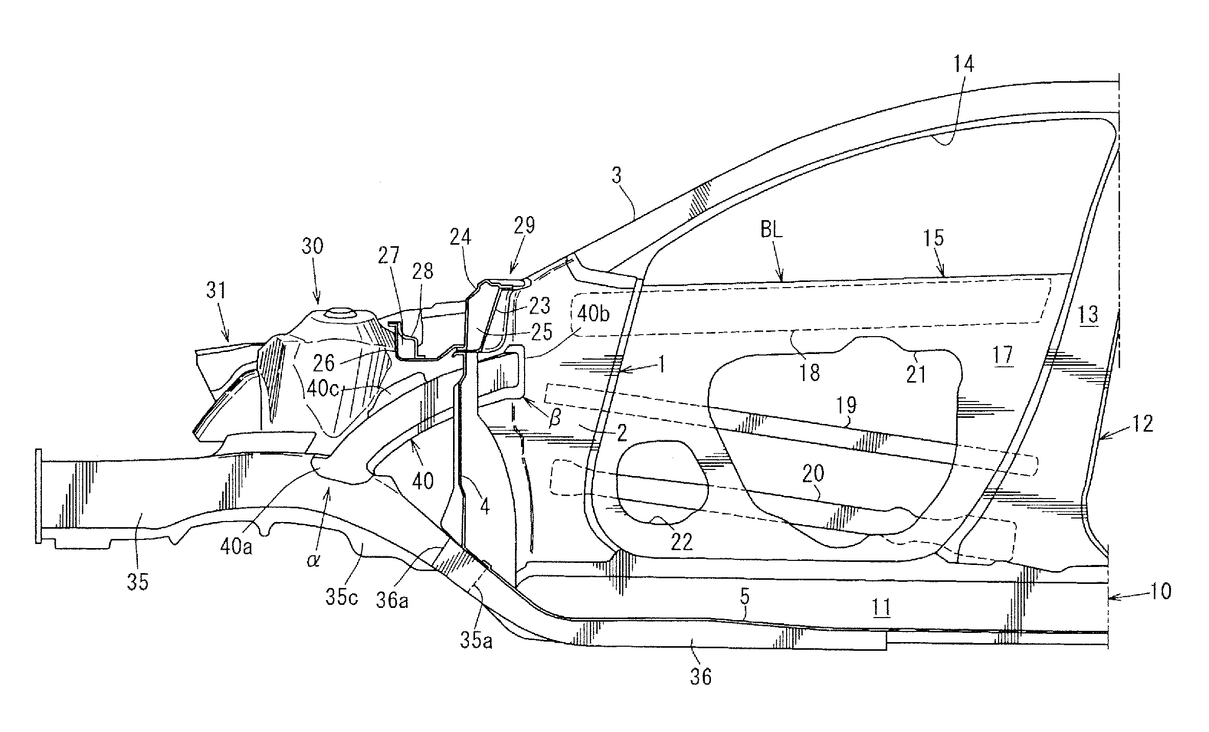
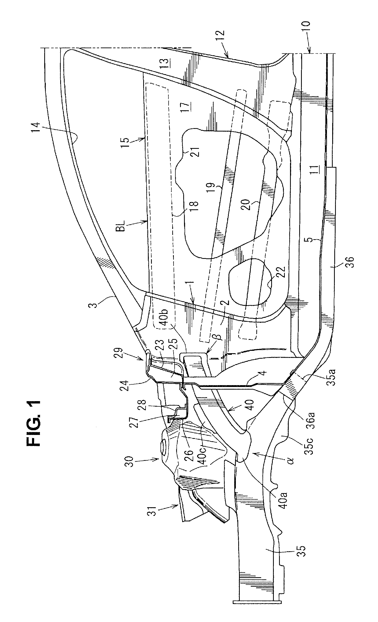
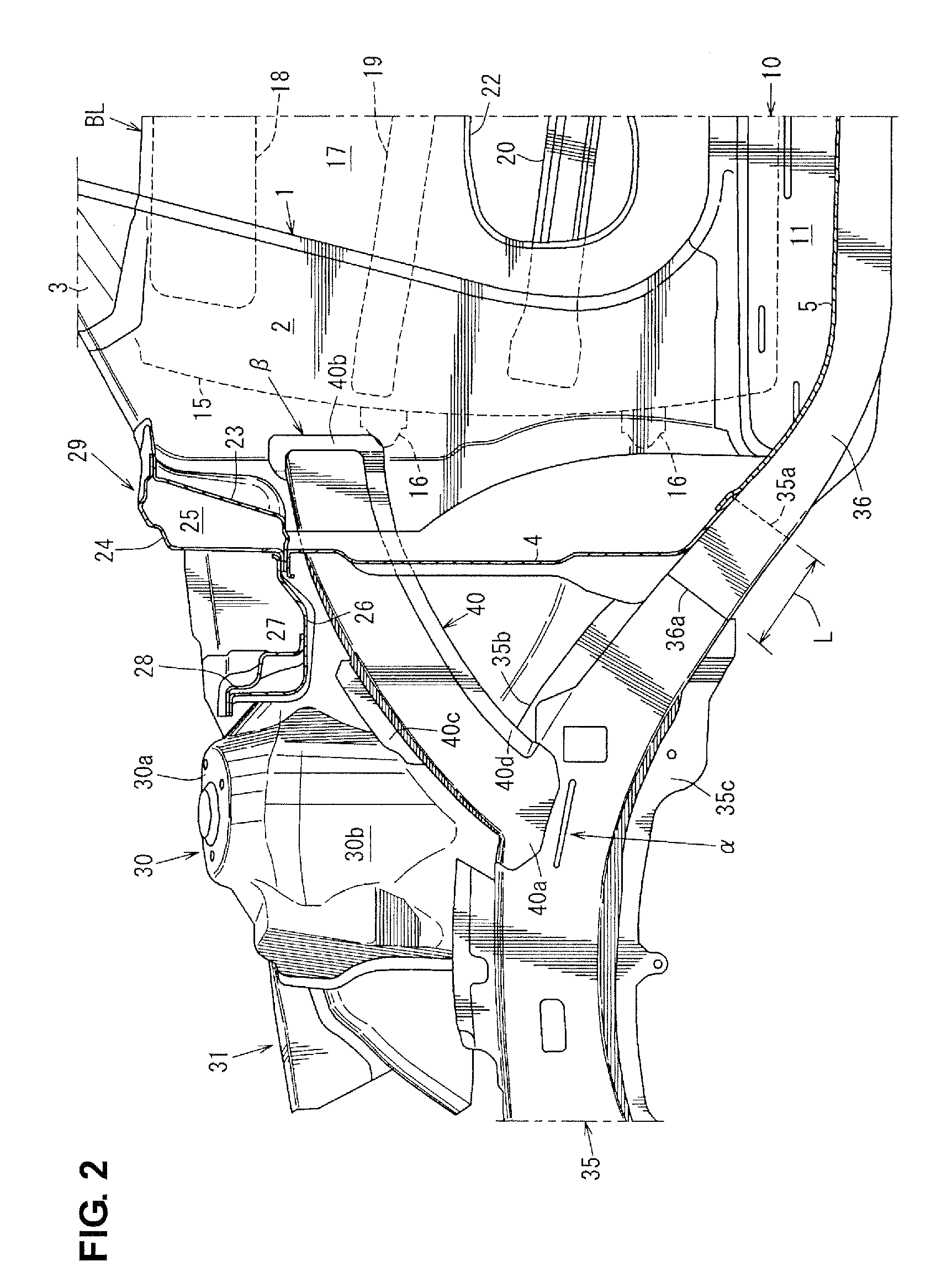
[0037]FIG. 1 is a side view showing a front structure of an automotive vehicle according to a first embodiment of the present invention. FIG. 2 is an enlarged view of a major part of FIG. 1. FIG. 3 is a perspective view of the major part of FIG. 1. FIG. 4 is a perspective view of a structure of FIG. 2, excluding a cowl front member and a cowl front cross member, when viewed from the top. FIG. 5 is a perspective view of the front structure, excluding a dash lower panel, when viewed from the back. FIG. 6 is a sectional view taken along line A-A of FIG. 4. FIG. 7 is a sectional view taken along line B-B of FIG. 4. FIG. 8 is a sectional view taken along line C-C of FIG. 4.

[0038]There is provided a pair of hinge pillars 1, 1 (only a right-side hinge pillar illustrated) as shown in FIGS. 1 and 2. The hinge pillar 1 is a vehicle-body rigidity member, which is comprised of a hinge pillar inner 2 and a hinge pillar outer that are joined, and has a closed pillar cross section that extends in ...

embodiment 2

[0091]An automotive vehicle according to a second embodiment comprises a pair of hinge pillars 103, 103 that is provided at both ends of a dash panel 102 so as to extend vertically, as shown in FIG. 12. Front doors are pivotally attached to the hinge pillars 103 (only one illustrated).

[0092]Apron reinforcements 104, 104 are provided so as to extend forward from upper end portions of the hinge pillars 103, respectively.

[0093]Front side frames 105, 105 are provided so as to extend longitudinally substantially in parallel to the apron reinforcements 104, 104 in a plan view and to be located inside away from the apron reinforcements 104, 104. Each front side frame 105 has a closed cross section that is formed with an inner member and an outer member having a U-shaped cross section and extends longitudinally.

[0094]A front-wheel house 106 is provided between the apron reinforcement 104 and the front side frame 105 in the vehicle width direction.

[0095]Plates 107, 107 are attached respectiv...


PUM


Abstract

A support frame is provided to extend upward and rearward from a portion of a front side frame near a suspension tower substantially straight and connect to an upper portion of a hinge pillar. Accordingly, there can be provided a front structure of an automotive vehicle that can properly restrain a forward deformation of a cabin by transmitting an impact load at a vehicle frontal crash to the hinge pillar efficiently.

Description

BACKGROUND OF THE INVENTION[0001]The present invention relates to a front structure of an automotive vehicle that comprises a hinge pillar, dash panel, suspension tower and front side frame.[0002]Conventionally, the above-described front structure of an automotive vehicle is known as disclosed in Japanese Patent Laid-Open Publication No. 2003-182633, for example. That is, as shown in FIG. 18, the front structure of an automotive vehicle comprises a pair of hinge pillars 91, 91 (only one illustrated in FIG. 18), a dash panel provided to interconnect the pair of hinge pillars 91, 91 so as to partition an engine room 92 from a vehicle compartment 93, a suspension tower 94 disposed in front of and away from the dash panel, and a front side frame 94 provided to extend in a vehicle longitudinal direction and connect to the suspension tower 94, a rear end of which bends downward and connects to a front portion of a floor frame. Herein, there is provided a gusset 99 as a support frame that ...

Claims


Application Information

Patent Timeline
Patent Type & Authority Applications(United States)
IPC IPC(8): B62D21/15
CPCB62D21/152B62D25/04B62D25/081B62D25/082B62D25/088
Inventor KIYOTAKE, SHINJIKIMURA, TAKAYUKIKOBASHI, MASANOBUMATSUOKA, HIDENORITERADA, SAKAYU
Owner MAZDA MOTOR CORP
Why Eureka
Try Eureka