Embedded magnet type motor

a technology of embedded magnets and motors, which is applied in the direction of magnetic circuit rotating parts, dynamo-electric machines, and shape/form/construction of magnetic circuits, etc., can solve the problems of excessive leakage fluxes passing through the outer bridge, reducing the effective flux of embedded magnet type motors, and increasing the number of parts. , to achieve the effect of reducing leakage fluxes, increasing torque, and preventing an increase in the number of parts

Inactive Publication Date: 2008-10-30
DENSO CORP
View PDF7 Cites 20 Cited by
  • Summary
  • Abstract
  • Description
  • Claims
  • Application Information

AI Technical Summary

Benefits of technology

[0006]An objective of the present invention is to provide an embedded magnet type motor which increases the torque while preventing an increase in the number of parts and reducing leakage fluxes.

Problems solved by technology

However, when two magnets are provided per one magnetic pole, the number of parts increases and parts management cost and assembly cost also increase.
Therefore, leakage fluxes passing through the outer bridges are excessive as a whole of the motor.
This reduces the effective fluxes of the embedded magnet type motor and obstructs the torque increase.

Method used


Image

  • Embedded magnet type motor
  • Embedded magnet type motor
  • Embedded magnet type motor

Examples


Embodiment Construction

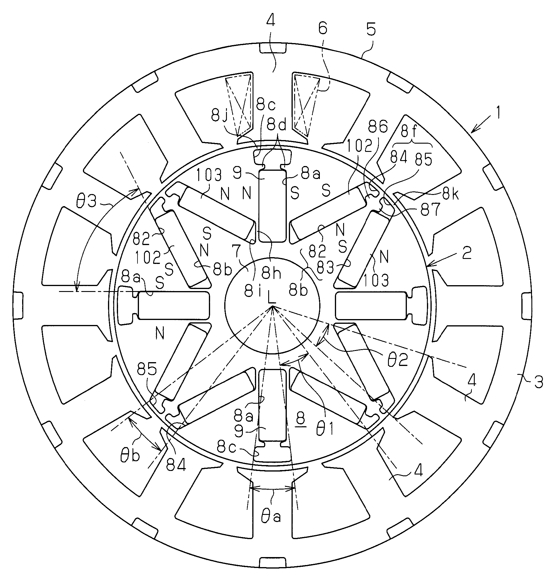
[0020]Hereinafter, an embodiment of the present invention will be described with reference to FIG. 1 through FIG. 6. As shown in FIG. 1, an embedded magnet type motor includes a stator 1 and a rotor 2.

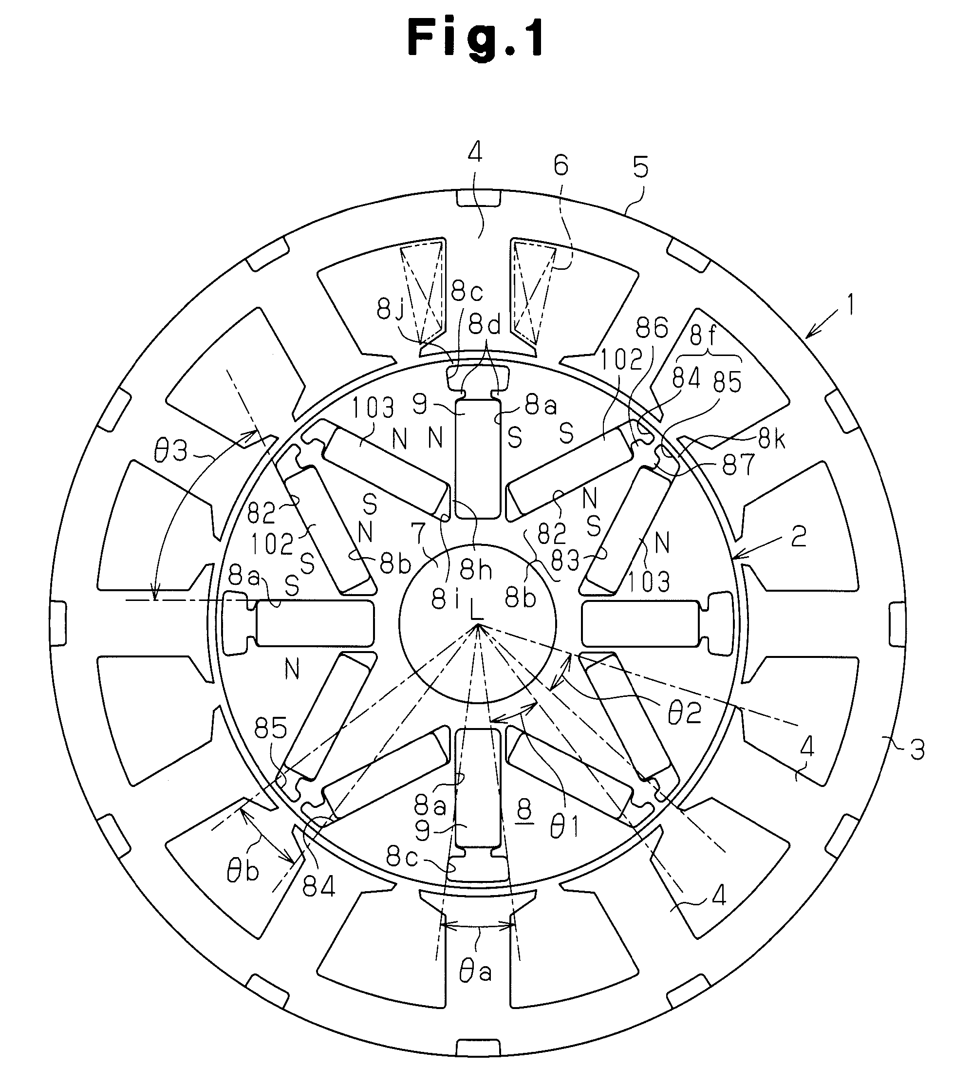
[0021]The stator 1 is cylindrical as a whole. The stator 1 includes a stator core 5 and a plurality of coils 6. The stator core 5 has a cylindrical portion 3 forming an outer shape and a plurality of teeth 4 arranged at equiangular intervals in the circumferential direction on the inner peripheral surface of the cylindrical portion 3. Each of these teeth extends toward the axial line L of the stator 1 from the inner peripheral surface of the cylindrical portion 3, that is, toward the radially inner side of the cylindrical portion 3. Each of the coils 6 is concentrically wound around a corresponding tooth 4 with an insulator (not shown). In FIG. 1, one coil 6 is shown by an alternate long and short double-dashed line. The stator core 5 of this embodiment includes twelve teeth 4. As show...


PUM


Abstract

An embedded magnet type motor is disclosed. The rotor core of the motor has radially extending first accommodation holes and V-shaped accommodation holes. Each V-shaped accommodation hole includes a second accommodation hole and a third accommodation hole. A first gap is formed in each first accommodation hole. The first gap is not occupied by the corresponding first magnet. A second gap is formed in each second accommodation hole. The second gap is not occupied by the corresponding second magnet. A third gap is formed in each third accommodation hole at a radially outer portion. The third gap is not occupied by the corresponding third magnet. Each second gap and the adjacent third gap form one V-shaped gap. The angular width θa of each first gap and the angular width θb of each V-shaped gap are determined to satisfy the expression: 0.60<θa / θb<1.60.

Description

BACKGROUND OF THE INVENTION[0001]The present invention relates to an embedded magnet type motor.[0002]Conventionally, a rotor core of an embedded magnet type motor has a plurality of accommodation holes aligned in the circumferential direction, and the accommodation holes perforate through the rotor core axially. In the accommodation holes, magnets are accommodated.[0003]In the embedded magnet type motor disclosed in Japanese Laid-Open Patent Publication No. 2005-51982, each of a plurality of magnetic poles includes a pair of magnets arranged in a V shape to protrude radially inward. Specifically, when the number of magnetic poles of the embedded magnet type motor is P, the number of magnets is 2P. With this construction, a higher torque can be realized in comparison with a motor in which one magnet is provided per one magnetic pole.[0004]However, when two magnets are provided per one magnetic pole, the number of parts increases and parts management cost and assembly cost also incre...

Claims


Application Information

Patent Timeline
Patent Type & Authority Applications(United States)
IPC IPC(8): H02K1/27
CPCH02K1/2766
Inventor NAKAYAMA, TAKAHIROITOH, HIROTAKATAKABE, YOSHIYUKIKOIDE, KEISUKENISHIKAWA, YOSHIHITO
Owner DENSO CORP
Why Eureka
Try Eureka