Method for driving liquid crystal display device, liquid crystal display device, and electronic device

a liquid crystal display and liquid crystal technology, applied in the direction of electric digital data processing, instruments, computing, etc., can solve the problems of difficult to achieve the desired gradation display, increase power consumption, and fluctuation of applied voltage, and achieve high video performance and image quality. the effect of high quality

Inactive Publication Date: 2008-10-30
SEMICON ENERGY LAB CO LTD
View PDF9 Cites 13 Cited by
  • Summary
  • Abstract
  • Description
  • Claims
  • Application Information

AI Technical Summary

Benefits of technology

[0037]By use of the driving methods of the present invention, high video performance can be realized. In addition, because the problems with overdriving can be solved, even higher image quality can be realized.

Problems solved by technology

However, a problem arises in that power consumption is increased in exchange for response speed.
Furthermore, although details of the phenomenon have not yet been explained, there is a problem in that fluctuations in the applied voltage arise directly after overdrive is performed.
When fluctuations in applied voltage are produced, display of a desired gradation becomes difficult to achieve.
In particular, in cases where high-level gradation display is performed, the effects of fluctuations in applied voltage cannot be ignored.
In other words, as higher levels of gradation are being displayed, problems occur in that the memory device becomes unnecessarily enlarged.

Method used


Image

  • Method for driving liquid crystal display device, liquid crystal display device, and electronic device
  • Method for driving liquid crystal display device, liquid crystal display device, and electronic device
  • Method for driving liquid crystal display device, liquid crystal display device, and electronic device

Examples


embodiment mode 1

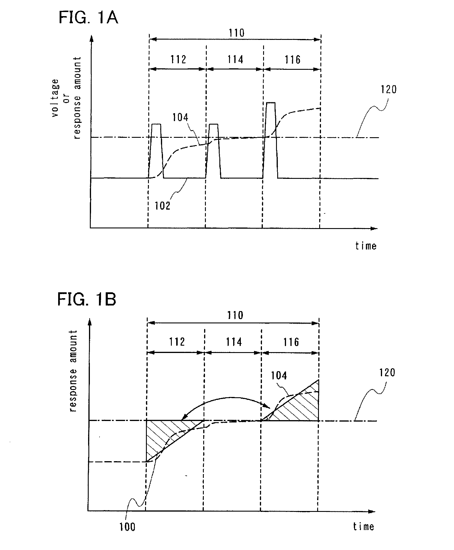
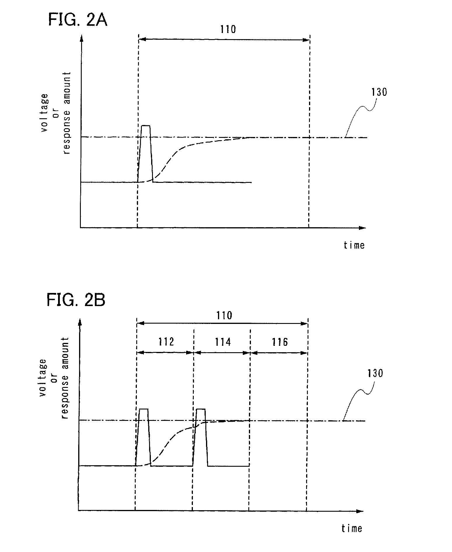
[0063]In the present embodiment mode, driving methods of the present invention and principles thereof will be described hereinafter using FIGS. 1A and 1B, FIGS. 2A and 2B, and FIGS. 3A and 3B.

[0064]In FIG. 1A, a relationship between voltage 102 (solid line) applied during a writing period of one pixel and a response amount 104 (dashed line) of the liquid crystal is shown for when a driving method of a liquid crystal display device of the present invention is used. Here, the response amount of the liquid crystal corresponds to display gradation for a liquid crystal display element. In addition, the horizontal axis represents time, and the vertical axis represents voltage and response amount. It is to be noted that in a liquid crystal display device in which active matrix driving is used, a signal voltage is input to a pixel electrode only during a selected period of a pixel, and a voltage input by a holding capacitor (also referred to as storage capacitor) is retained for periods the...

embodiment mode 2

[0086]In the present embodiment mode, a driving method differing from the method described in Embodiment Mode 1 will be described using FIG. 4.

[0087]First, one frame period is divided up into an n (n: integer, n≧3) number of subframe periods (FIG. 4). In the present embodiment mode, for sake of simplicity, a case in which one frame period 410 is divided into three subframe periods (a first subframe period 412, a second subframe period 414, and a third subframe period 416) will be described; however, the present invention is not to be taken as being limited to this case. It is to be noted that because rewriting of a pixel is generally performed at 60 Hz in a liquid crystal display device, the length of one frame period comes to be (1 / 60) s. In the present invention, because one frame period is further divided up into three subframe periods, driving comes to be performed at 180 Hz. That is, the length of one subframe period is (1 / 180) s. Needless to say, in cases where one frame perio...

embodiment mode 3

[0101]In the present embodiment mode, another driving method of the present invention will be described using FIGS. 5A and 5B.

[0102]First, one frame period is divided up into an n (n: integer, n≧3) number of subframe periods (FIG. 5). In the present embodiment mode, for sake of simplicity, a case in which one frame period is divided into four subframe periods will be described; however, the present invention is not to be taken as being limited to this case. Of course, cases in which one frame period is divided into three subframe periods can be applied, as well. It is to be noted that because rewriting of a pixel is generally performed at 60 Hz in a liquid crystal display device, the length of one frame period comes to be (1 / 60) s. In the present invention, because one frame period is further divided up into four subframe periods, driving comes to be performed at 240 Hz. That is, the length of one subframe period is (1 / 240) s. Needless to say, in cases where one frame period is divi...


PUM


Abstract

An object of the present invention is to provide a driving method of a liquid crystal display device for improvement of image quality and a liquid crystal display device in which the driving method is used. One frame period is divided up into an n (n: integer, n≧3) number of periods (hereinafter referred to as subframe periods). Furthermore, a voltage is applied to a liquid crystal so as to correct for a loss in luminance resulting from response speed of the liquid crystal. The voltage for correction is applied during subframe periods other than the first subframe period.

Description

BACKGROUND OF THE INVENTION[0001]1. Field of the Invention[0002]The present invention relates to driving methods for liquid crystal display devices in order to improve image quality and liquid crystal display devices and electronic devices in which the driving methods are used.[0003]2. Description of the Related Art[0004]In recent years, replacement of display devices in which conventional cathode-ray tubes with liquid crystal display devices are used as well as employment of liquid crystal display devices in miniature electronic devices has been progressing rapidly. Here, liquid crystal display device refers to a display device in which the alignment orientation of liquid crystal molecules is changed by application of a voltage to the liquid crystal molecules which are interposed between substrates and changes in optical characteristics produced thereby are used.[0005]For a typical liquid crystal display device, for example, twisted nematic (TN) liquid crystal display devices can b...

Claims


Application Information

Patent Timeline
Patent Type & Authority Applications(United States)
IPC IPC(8): G09G3/36
CPCG09G3/2025G09G3/2081G09G3/3406G09G3/3611G09G2340/16G09G2300/0465G09G2310/0237G09G2320/0247G09G2320/0252G09G3/3648G09G3/36G09G3/20G02F1/133
Inventor ARASAWA, RYOFUKUTOME, TAKAHIRO
Owner SEMICON ENERGY LAB CO LTD
Why Eureka
Try Eureka