Generation of a particle system using a geometry shader

a particle system and shader technology, applied in the field of computer graphics, can solve the problems of processing bottlenecks, cpu/system memory strain on bandwidth available between gpu and cpu,

Inactive Publication Date: 2008-10-30
NVIDIA CORP
View PDF8 Cites 29 Cited by
  • Summary
  • Abstract
  • Description
  • Claims
  • Application Information

AI Technical Summary

Problems solved by technology

However, objects without such definition, such as fire, an explosion, smoke, clouds, fog, mist, rain, snow and other “fuzzy” objects present challenges.
However, sending the entire set of vertices to be rendered may be a strain on bandwidth available between a CPU / system memory and the GPU.
Processing bottlenecks can occur, for instance, if the graphics subsystem does not provide sufficient bandwidth to communicate all of the vertices and their associated attributes through various units of the pipeline.

Method used


Image

  • Generation of a particle system using a geometry shader
  • Generation of a particle system using a geometry shader
  • Generation of a particle system using a geometry shader

Examples


Embodiment Construction

[0027]This description provides exemplary embodiments only, and is not intended to limit the scope, applicability or configuration of the invention. Rather, the ensuing description of the embodiments will provide those skilled in the art with an enabling description for implementing embodiments of the invention. Various changes may be made in the function and arrangement of elements without departing from the spirit and scope of the invention as set forth in the appended claims.

[0028]Thus, various embodiments may omit, substitute, or add various procedures or components as appropriate. For instance, it should be appreciated that in alternative embodiments, the methods may be performed in an order different than that described, and that various steps may be added, omitted or combined. Also, features described with respect to certain embodiments may be combined in various other embodiments.

[0029]It should also be appreciated that the following systems, methods, and software may be a c...


PUM


Abstract

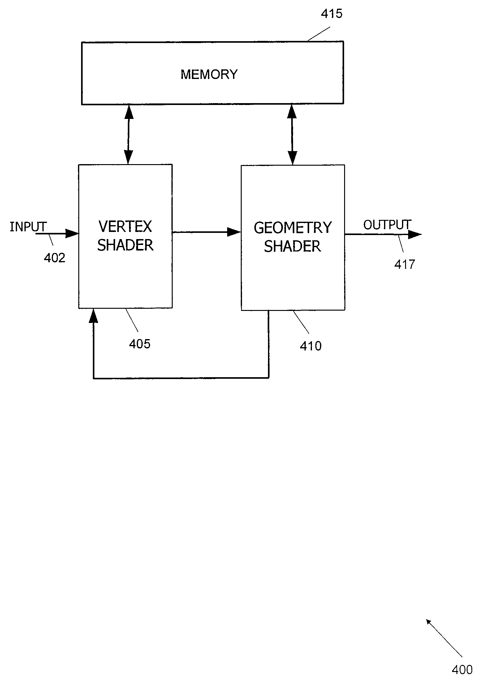
A geometry shader of a graphics processor is configured to generate at least a portion of a particle system. The geometry shader receives vertex data including a reference set of vertices. The geometry shader also receives control data including information on how to create additional vertices for the particle system using the vertex data. The geometry shader processes the vertex data and control data to generate the additional vertices for the particle system. In some embodiments, the control data also includes information on other attributes of the generated vertices.

Description

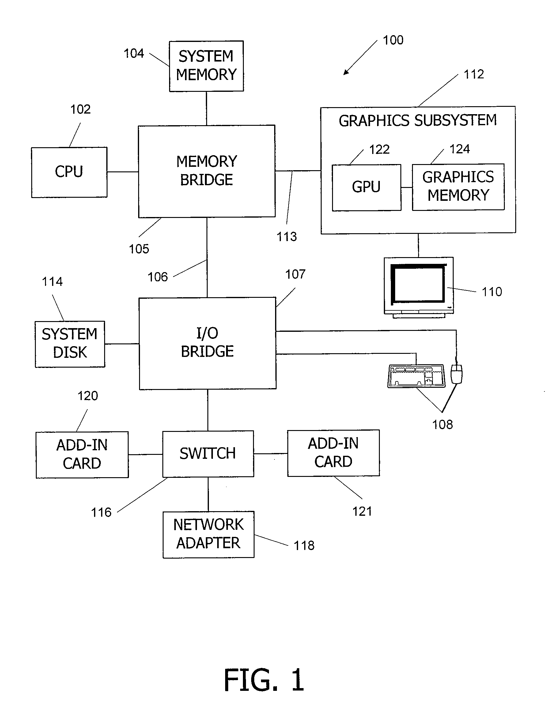
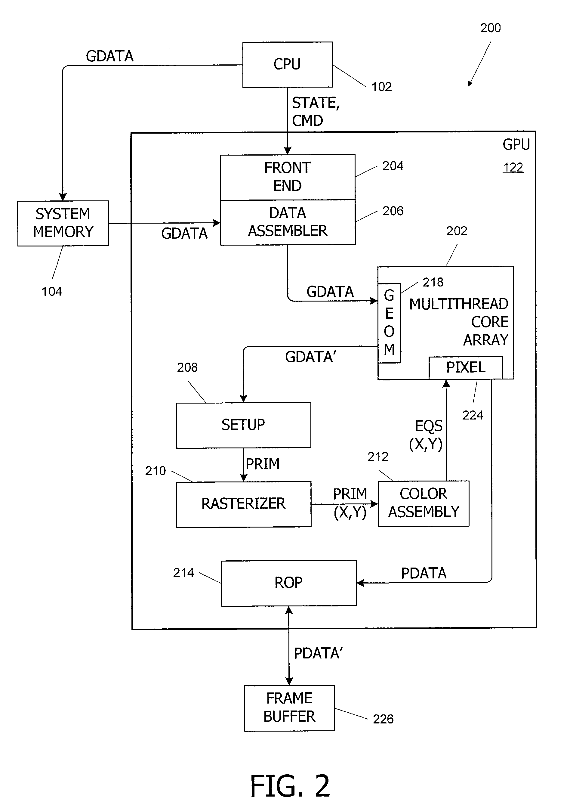
BACKGROUND OF THE INVENTION[0001]The present invention relates in general to computer graphics, and in particular to the generation of a particle system in a graphics processor.[0002]Many computer generated images are created by mathematically modeling the interaction of light with a three-dimensional (3D) scene from a given viewpoint and projecting the result onto a two-dimensional (2D) “screen.” This process, called rendering, generates a 2D image of the scene from the given viewpoint and is analogous to taking a digital photograph of a real-world scene.[0003]Certain traditional modeling techniques are often better at creating objects with well-defined surfaces. However, objects without such definition, such as fire, an explosion, smoke, clouds, fog, mist, rain, snow and other “fuzzy” objects present challenges. In computer graphics, these objects may be rendered using a technique referred to as a particle system. In a particle system, a fuzzy object is modeled as a group of parti...

Claims


Application Information

Patent Timeline
Patent Type & Authority Applications(United States)
IPC IPC(8): G06T15/00
CPCG06T15/005
Inventor RAMEY, WILLIAM ORVILLEMORETON, HENRY PACKARDROGERS, DOUGLAS H.
Owner NVIDIA CORP
Why Eureka
Try Eureka