Optical apparatus

a technology of optical equipment and optical components, applied in the field of optical equipment, can solve the problems of unfavorable weight and large unfavorable compactness, unfavorable expansion, etc., and achieve the effects of being lightweight, compact, and reducing the size of the whole optical equipmen

Inactive Publication Date: 2008-10-30
OLYMPUS CORP
View PDF26 Cites 8 Cited by
  • Summary
  • Abstract
  • Description
  • Claims
  • Application Information

AI Technical Summary

Benefits of technology

[0006]Accordingly, an object of the present invention is to provide an optical apparatus using a variable-optical-characteristic optical element whereby focusing, zooming or the like can be effected without moving a lens or the like and the whole optical apparatus can be arranged in a lightweight structure.
[0007]Another object of the present invention is to provide optical apparatus, e.g. a digital camera and a system using it, which are compact, lightweight and superior in function upgradability and expandability.

Problems solved by technology

This causes the whole optical apparatus to become unfavorably heavy in weight and large in size.
Therefore, the conventional digital cameras have the disadvantage that they cannot be made compact and hence become unfavorably heavy.
Further, because the definition (pixel density) of solid-state image pickup devices is becoming increasingly higher, the overall functions of digital cameras rapidly become obsolescent.
In this regard, an image pickup system using the conventional method in which an optical system consisting of lenses and other optical elements is driven by a motor is large in size and heavy in weight and suffers unfavorably high power consumption.

Method used


Image

  • Optical apparatus
  • Optical apparatus
  • Optical apparatus

Examples


Embodiment Construction

[0270]Embodiments of the optical apparatus according to the present invention will be described below.

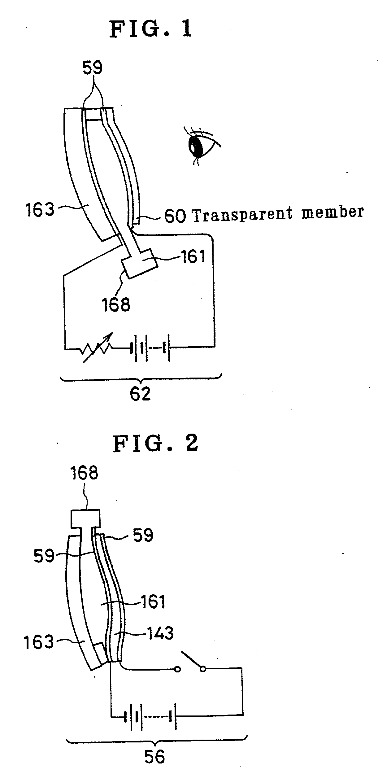
[0271]FIG. 1 is a diagram for describing the arrangement and operation of an example of a variable-focus lens 62 for use in an optical product according to the present invention, which uses electrostatic force. A transparent member 60 is deformable under application of a voltage. The deformation of the transparent member 60 causes a change in the configuration of the lens, thereby allowing a variable-focus system to be realized. In FIG. 1, reference numeral 59 denotes transparent electrodes, and reference numeral 161 denotes a transparent fluid. Further, reference numeral 163 denotes a transparent substrate, and reference numeral 168 denotes a fluid reservoir. The transparent substrate 163 and the transparent member 60 are positioned to face each other. The transparent electrodes 59 are provided on the respective inner sides of the transparent substrate 163 and the transparent membe...


PUM


Abstract

An optical apparatus uses a variable-optical-characteristic optical element whereby focusing, zooming or the like can be effected without moving a lens or the like and the whole optical apparatus can be arranged in a lightweight structure. The user wears a power transmitting unit 303 by hanging it from his / her neck, for example. The power transmitting unit 303 may be put in a clothes pocket or the like. The power transmitting unit 303 may be placed somewhere around the user. In the power transmitting unit 303, a transmitting circuit 305 is driven by a power supply 304 to send an electromagnetic wave from a transmitting antenna 306 toward variable-focus eyeglasses 302. The variable-focus eyeglasses 302 have a receiving antenna 307 provided on eyeglass frames 308 to receive the electromagnetic wave sent from the power transmitting unit 303. The received electromagnetic wave is, for example, boosted in voltage and rectified to drive the variable-focus lenses.

Description

CROSS REFERENCE TO RELATED APPLICATIONS[0001]This application is a division of U.S. patent application Ser. No. 09 / 957,471, filed Sep. 21, 2001, which claims priority to Japanese application nos. 2000-388165, filed Dec. 21, 2000 and 2001-009951, filed Jan. 18, 2001, the entire contents of all of which are incorporated herein by reference.BACKGROUND OF THE INVENTION[0002]The present invention relates to optical apparatus and, more particularly, to optical apparatus using a variable-optical-characteristic optical element.[0003]Conventionally, lenses, mirrors and so forth are used in optical apparatus. These optical elements have invariable optical characteristics. That is, the focal length thereof, for example, is not variable. Therefore, in order to effect focusing or zooming, for example, it is necessary to move lenses, etc. This causes the whole optical apparatus to become unfavorably heavy in weight and large in size.[0004]Conventional digital cameras have an arrangement in which ...

Claims


Application Information

Patent Timeline
Patent Type & Authority Applications(United States)
IPC IPC(8): G02B26/08G02B15/14G02B3/14G02B26/00H04N5/225
CPCG02B3/14G02B26/00G02B26/0825H04N5/2251H04N5/2254H04N23/673
Inventor NISHIOKA, KIMIHIKOMURAKAMI, MIYUKI
Owner OLYMPUS CORP
Why Eureka
Try Eureka