
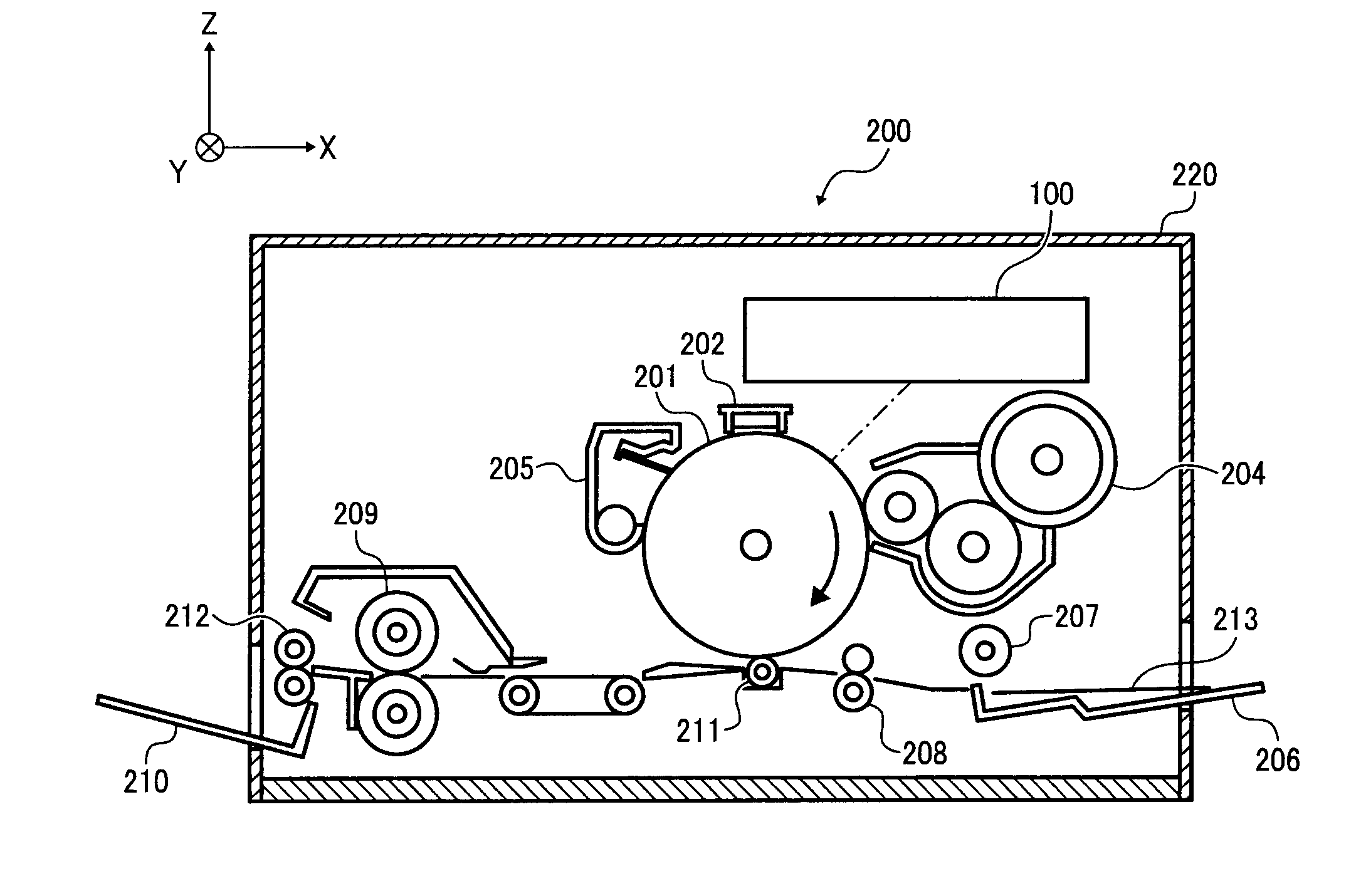
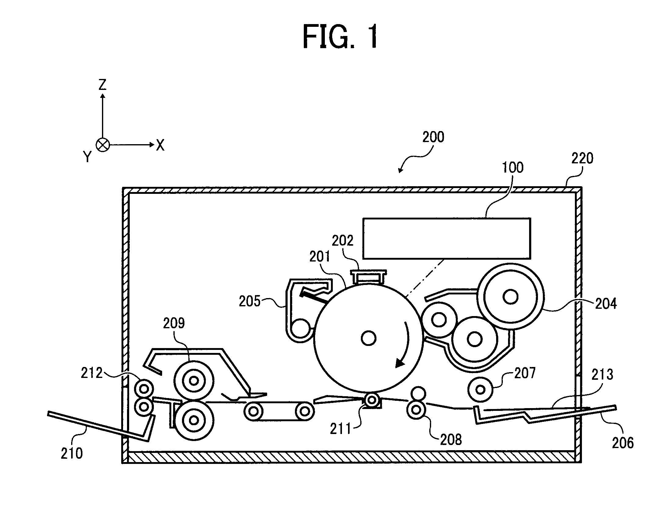
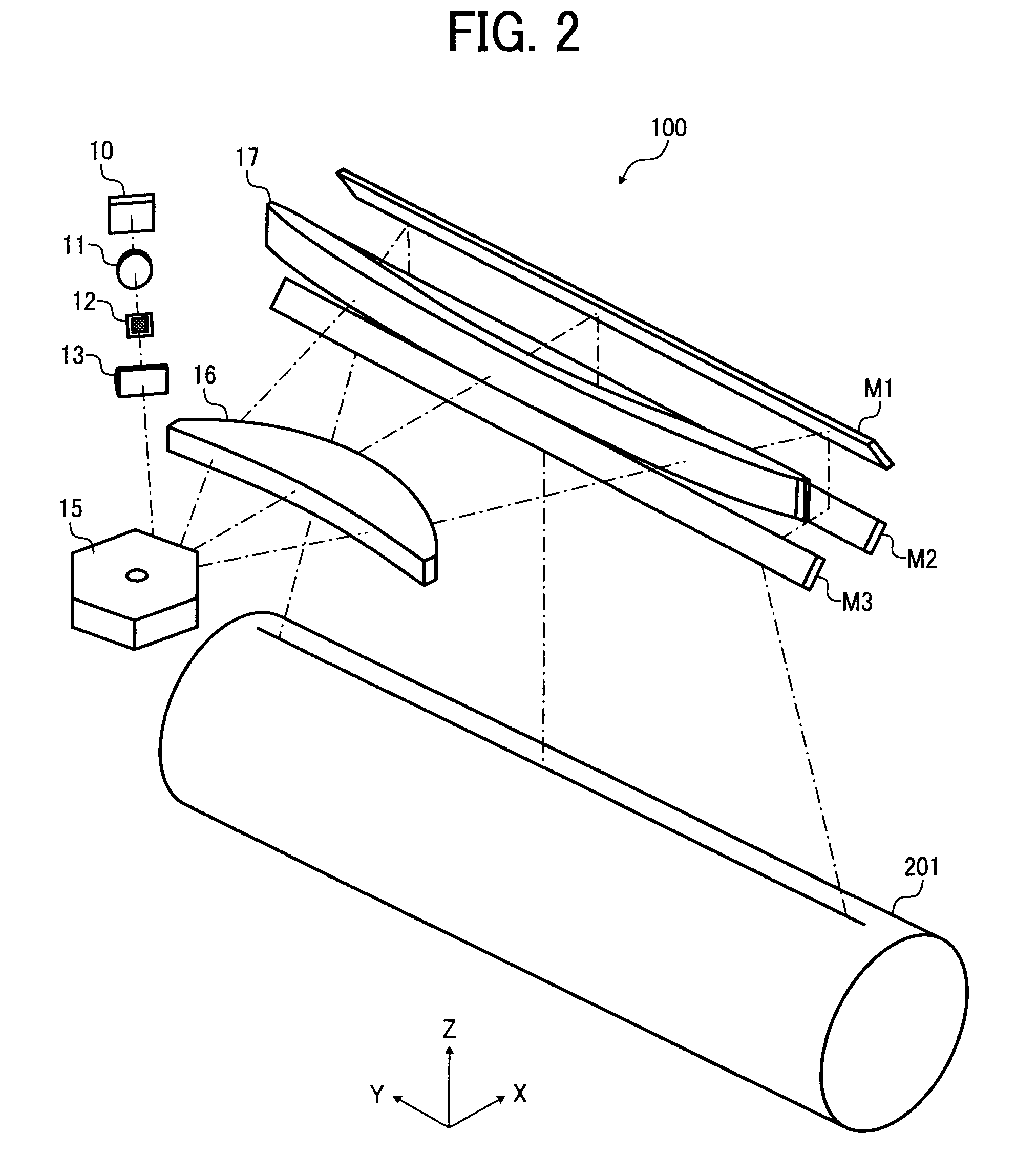
Light scanning device and image forming apparatus

Inactive Publication Date: 2008-10-30
RICOH KK
View PDF26 Cites 35 Cited by
  • Summary
  • Abstract
  • Description
  • Claims
  • Application Information

AI Technical Summary

Benefits of technology

[0010]An object of the present invention is to provide a light scanning device that is smaller and has lower cost and be able to seek improvement in light beam use efficiency.

Problems solved by technology

However, an output from VCSEL is approximately 1˜2 mW and is low in comparison to an edge-emitting type laser or the like.
By splitting a portion of the scanning light by an above-described beam splitter or the like, it is problematic in that loss is generated in light quantity of light beams essentially necessary for scanning.
Furthermore, the scanning light, when passing the beam splitter, receives the influence of surface precision of a reflecting surface or a deflected surface of the beam splitter so that positional variation is generated on a beam spot of the scanning light, and it is problematic in that optical property deteriorates.
However, if the light receiving surface becomes large, the responsiveness of the light receiving element deteriorates, furthermore, it is problematic that the device becomes larger and requires higher cost.

Method used


Image

  • Light scanning device and image forming apparatus
  • Light scanning device and image forming apparatus
  • Light scanning device and image forming apparatus

Examples


modified example 1

[0062]In addition, although in the present embodiment, the aperture member 12 having a flat reflective surface to reflect light beams for monitoring use is described, the present invention is not limited thereto. As shown in FIG. 7, the aperture member 12 can have a curved surface having a focal point. In such a case, the light receiving element 20 is disposed such that the light receiving surface of the light receiving element 20 is situated in a focal point position of the reflective surface or the vicinity thereof. Thereby it is no longer necessary to dispose the condensing lens 21 and lessening the number of parts become possible. In addition, by enlarging the degree of curvature of the curved reflective surface to collect light beams in the vicinity of the aperture member 12, the optical path from the light source 10 to the light receiving element 20 can be shortened so that it is possible for the light scanning device to become smaller. In a modified example 1, the reflective ...

modified example 2

[0063]In addition, as shown in FIG. 8, a separation optical element 23 that separates a portion of the light beams is disposed on the optical path between the light source 10 and the coupling lens 11, and the light beam LB2 for monitoring use separated by the separation optical element 23 can be received by the light receiving element 20. The separation optical element 23, likewise to the above-described aperture member 12, is a member in a plate form with an opening 23a formed in the center. The surface on the side where light beams transmitting through the coupling lens 11 are incident is a reflective surface formed by having, for example, aluminum or the like vapor deposited.

[0064]As described above, by disposing the separation optical element 23 between the light source 10 and the coupling lens 11, the degree of freedom of layout of the coupling lens 11 and the following components of the optical system increases and it is possible for the monitoring optical system to be small-s...

modified example 3

[0065]In addition, in the case of disposing the separation optical element 23 that separates a portion of the light beams on the optical path between the light source 10 and the coupling lens 11, as shown in FIG. 9, the reflective surface of the separation optical element 23 can be a curved surface having a focal point. In such a case, the light receiving element 20 is disposed such that the light receiving surface of the light receiving element 20 is situated in a focal point position of the reflective surface or the vicinity thereof. Thereby it is no longer necessary to dispose the condensing lens 21 and lessening the number of parts becomes possible. In addition, by enlarging the degree of curvature of the curved reflective surface to collect light beams in the vicinity of the separation optical element 23, the optical path from the light source 10 to the light receiving element 20 can be shortened so that it is possible for the light scanning device to become smaller. In a modif...


PUM


Abstract

A light scanning device, which scans a surface to be scanned in a main scanning direction by a plurality of light beams, includes a light source including a plurality of light emitting parts that are arrayed two-dimensionally to emit the light beams, a separation optical system that separates a portion of the light beams emitted respectively from the plurality of light emitting parts, and a light receiving element that receives the portion of the light beams separated by the separation optical system. The separation optical system is a reduction system.

Description

PRIORITY CLAIM[0001]This application claims priority from Japanese Patent Application No. 2007-113670, filed with the Japanese Patent Office on Apr. 24, 2007, the contents of which are incorporated herein by reference in their entirety.BACKGROUND OF THE INVENTION[0002]1. Field of the Invention[0003]The present invention relates to a light scanning device and an image forming apparatus, more specifically, to a light scanning device that scans a surface to be scanned by a plurality of light beams, and an image forming apparatus including the light scanning device.[0004]2. Description of the Related Art[0005]There is known an image forming apparatus that forms an image using Carlson's process, for example, a surface of a rotating photoconductive drum is scanned by light beams so that a latent image is formed on the surface of the rotating photoconductive drum. The image forming apparatus is configured to form an image by fixing a toner image obtained by visualizing the latent image to ...

Claims


Application Information

Patent Timeline
IPC IPC(8): G03G15/04
CPCG03G15/0409G03G15/043G03G15/0435G03G15/326H04N2201/0082H04N1/1135H04N1/12H04N1/1911G03G2215/0407
Inventor ARAI, NOBUYUKIHAYASHI, YOSHINORI
Owner RICOH KK
Features
  • Generate Ideas
  • Intellectual Property
  • Life Sciences
  • Materials
  • Tech Scout
  • Unparalleled Data Quality
  • Higher Quality Content
  • 60% Fewer Hallucinations
Learn More