Aerofoil members for a turbomachine

a technology of aerofoil and turbomachine, which is applied in the direction of machines/engines, wind motors with perpendicular air flow, climate sustainability, etc., can solve the problems of complex flow field within sectoral passages, adversely affecting the fluid flow downstream, and energy dissipation

Active Publication Date: 2008-10-30
ROLLS ROYCE PLC
View PDF49 Cites 31 Cited by
  • Summary
  • Abstract
  • Description
  • Claims
  • Application Information

AI Technical Summary

Benefits of technology

[0016]The present invention is at least partly based on the realisation that reverse compound lean can be used to control or alter the flow fields in a turbomachine. In general terms, the present invention provides a circumferential row of ae...

Problems solved by technology

The flow field within the sectoral passages is complex and includes a number of secondary vortical flows, which are a major source of energy loss.
Not only is there energy dissipation in the secondary flows themselves, but they can also affect adversely the fluid flow downstream because they cause deviation of the exit angles of the flow from the row of aerofoil members.
These effects gi...

Method used


Image

  • Aerofoil members for a turbomachine
  • Aerofoil members for a turbomachine
  • Aerofoil members for a turbomachine

Examples


Embodiment Construction

[0035]Before describing aspects, optional features and detailed embodiments of the present invention, it is helpful to provide an overview of turbomachine geometry and to define certain terms useful for understanding the present invention.

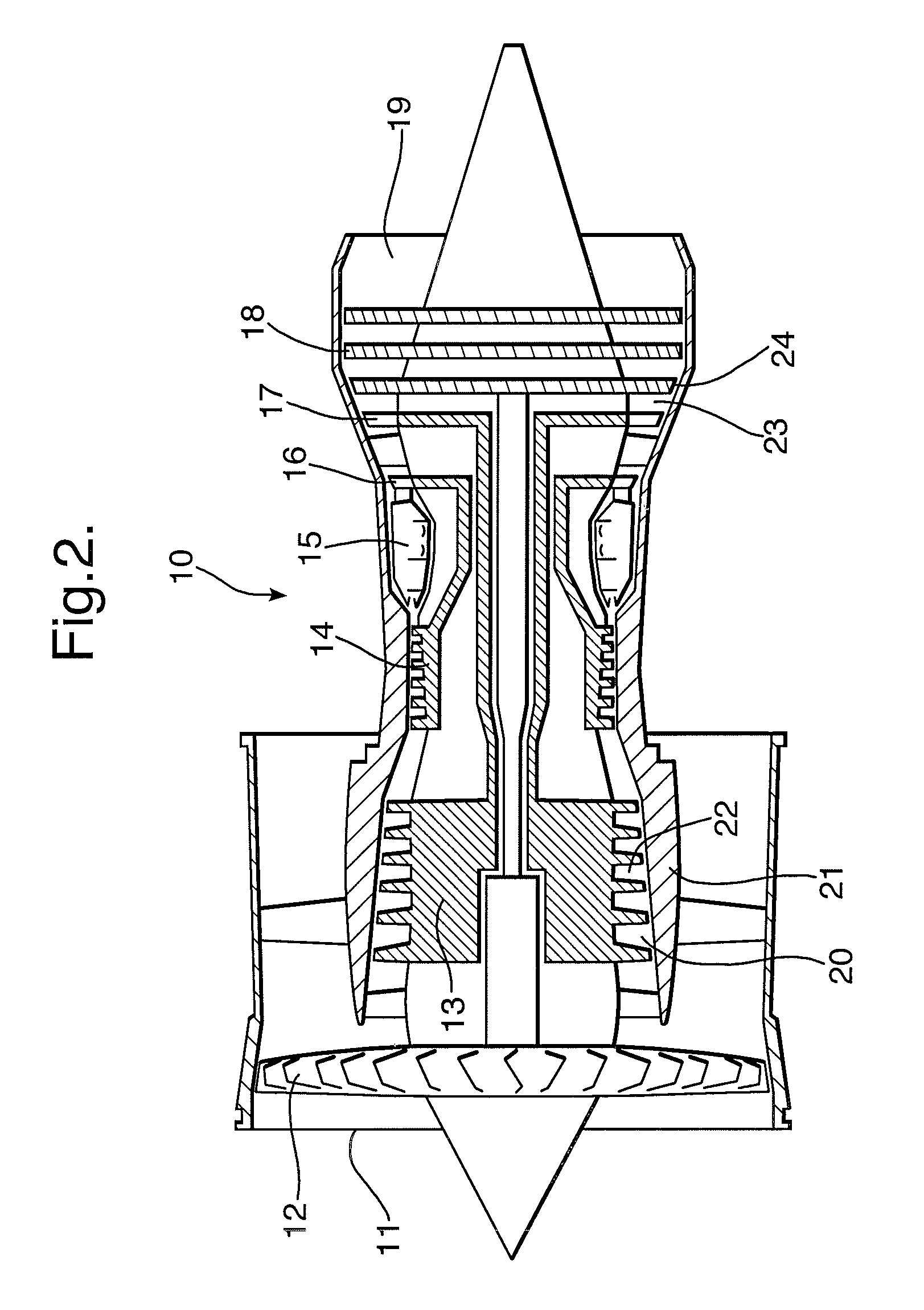
[0036]The gas turbine 10 of FIG. 2 is an example of a turbomachine of generally conventional configuration, comprising an air intake 11, ducted fan 12, intermediate and high pressure compressors 13,14 respectively, combustion chambers 15, high, medium and low pressure turbines 16,17,18 respectively, rotating independently of each other and an exhaust nozzle 19. The intermediate and high pressure compressors 13,14 are each made up of a number of stages each formed by a row of fixed guide vanes 20 projecting radially inwards from the casing 21 into the annular gas duct through the compressor and a following row of compressor blades 22 projecting radially outwards from rotary drums coupled to the hubs of the high and medium pressure turbines 16,17 res...


PUM


Abstract

A circumferential row of aerofoil members span an annular duct for carrying a flow of compressible fluid. The duct is centred on the axis of a turbomachine. Pressure and suction surfaces of neighbouring aerofoil members bound respective sectoral passages which receive the flow of compressible fluid. The row comprises at least one radial endwall to which the tangent to the trailing edge of each aerofoil member at midspan is substantially orthogonal. Each aerofoil member has reverse compound lean. Each aerofoil member further has a leading edge which has a position at the endwall which is upstream of its position at midspan.

Description

CROSS-REFERENCE TO RELATED APPLICATION[0001]This application is entitled to the benefit of British Patent Application No. GB 0704426.6 filed on Mar. 8, 2007.FIELD OF THE INVENTION[0002]The present invention relates to a turbomachine in which there are one or more rows of aerofoil members in an annular duct centred on the axis of the turbomachine, the duct carrying, in use, a flow of compressible fluid. The invention is particularly concerned with improving the control of the fluid flow past rows of such aerofoil members, which may be fixed vanes or blades rotating about the central axis of the duct.BACKGROUND OF THE INVENTION[0003]In typical turbomachines, each row of aerofoil members divides a duct into a series of sectoral passages, each bounded by the opposed suction and pressure surfaces of a neighbouring pair of members and the radially inner and outer walls of the duct. The flow field within the sectoral passages is complex and includes a number of secondary vortical flows, wh...

Claims


Application Information

Patent Timeline
IPC IPC(8): F01D1/02
CPCF01D5/141F01D5/143F01D5/145F05D2270/17Y02T50/60
Inventor HARVEY, NEIL WILLIAMSTOKES, MARK RICHARDBAGSHAW, DAVID ANDREW
Owner ROLLS ROYCE PLC
Why Eureka
Try Eureka