Apparatus for Manufacturing a Face Gear

a technology of gear teeth and manufacturing apparatus, which is applied in the direction of gear teeth, gear manufacturing apparatus, manufacturing tools, etc., can solve the problems of only applying process to materials with suitable hardness and metal cutting characteristics, and the shaper tool cannot effectively cut, so as to prevent the burning of gear teeth during grinding

Inactive Publication Date: 2008-10-30
HELIGEAR ACQUISITION CO
View PDF7 Cites 22 Cited by
  • Summary
  • Abstract
  • Description
  • Claims
  • Application Information

AI Technical Summary

Benefits of technology

[0009]Any of the described embodiments of the present invention may further include a high-pres

Problems solved by technology

Historically, the transmission of power through a face gear set has been limited to relatively low levels because of two factors: 1) the tooth profile of the mating gears has been generated by shaper cutting; and 2) although an acceptable tooth profile could be generated, the tooth produced by the shaping operation did not have a hardened surface.
In the past, any operation performed on the face gear set to harden the surface of the shaped teeth tended to distort

Method used


Image

  • Apparatus for Manufacturing a Face Gear
  • Apparatus for Manufacturing a Face Gear
  • Apparatus for Manufacturing a Face Gear

Examples


Embodiment Construction

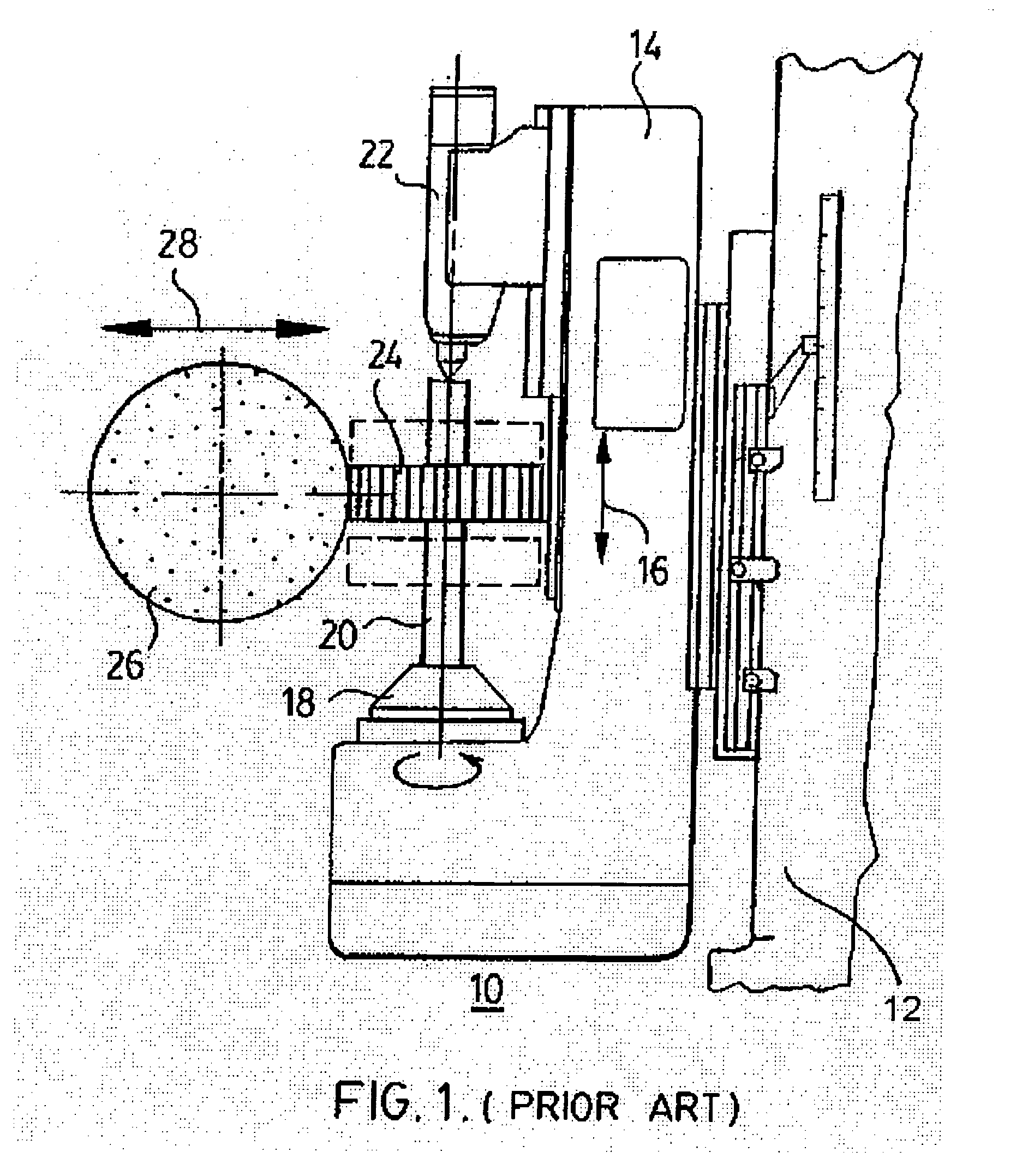
[0027]Turning now to the drawings, wherein like numerals represent like parts, the numeral 10 represents generally a prior art spur gear grinding apparatus. A machine 12 (partially shown) is provided with a moveable carrier 14 that is capable of executing rectilinear motion, as indicated by a double arrow 16. Carrier 14 is provided with a gear driving head 18, which is connected to lead shaft 20. The end of shaft 20 remote from driving head 18 is centered in tailstock 22 in order to stabilize shaft 20. A spur gear 24 is mounted on shaft 20 so as to be controllably rotated by driving head 18.

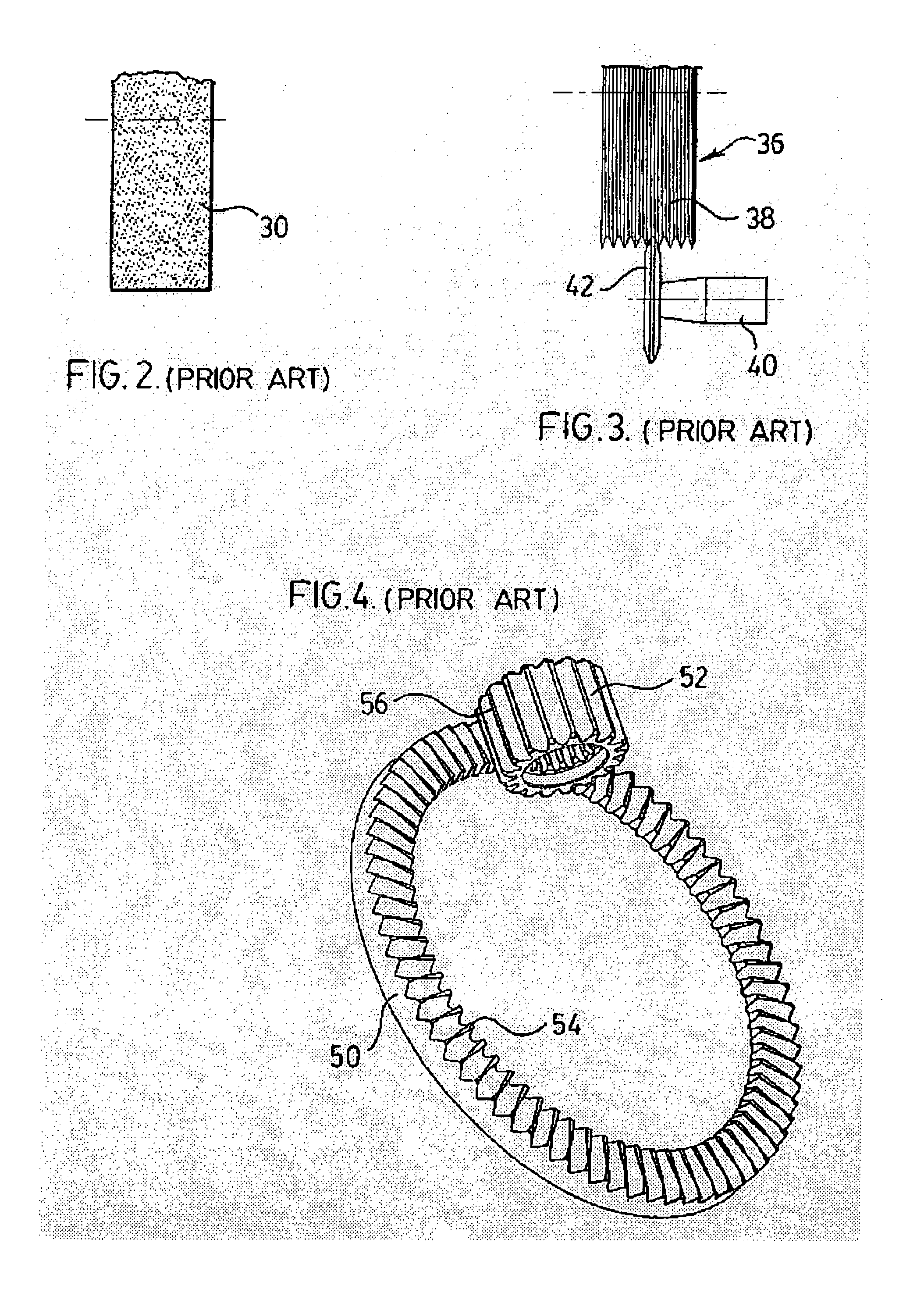
[0028]A spur gear grinding wheel 26 is shown engaging the peripheral surface of spur gear 24. Grinding wheel 26 takes the same form as grinding wheel 36, shown in FIG. 3, and must be capable of movement toward and away from gear 24 as indicated by double arrow 28. The rotation of the grinding wheel is coordinated with the rotation of the spur gear.

[0029]To produce a ground spur gear, the grinding...


PUM

PropertyMeasurementUnit
Pressureaaaaaaaaaa
Shapeaaaaaaaaaa
Widthaaaaaaaaaa

Abstract

A precision grinding apparatus for grinding face gears having a gear table portion controllably driven for rotation about a central axis, and also being movable in a vertical plane along an axis in a controlled manner. The apparatus further includes a case hardened face mounted on the gear table portion. A grinding wheel mounted on the apparatus has controlled driven rotation about a central axis C, and is provided with a grinding surface of predetermined shape. The grinding wheel is movable in a controlled manner toward and away from the gear along a feed axis V, the grinding wheel being movable in a controlled manner in a tangential direction with respect to the gear and orthogonal to the feed axis along a tangential feed axis wherein the motion of the grinding wheel in the C, V and TF axes, and movement of the gear in B and W axes, is controlled by a central control means.

Description

BACKGROUND OF THE INVENTION[0001]The present invention is directed generally to a method and apparatus for the development of face gears and, more specifically, to a method and apparatus for the development of face gears suitable for high power transmission.[0002]The development of face gears for high power transmission is a relatively recent phenomenon. Historically, the transmission of power through a face gear set has been limited to relatively low levels because of two factors: 1) the tooth profile of the mating gears has been generated by shaper cutting; and 2) although an acceptable tooth profile could be generated, the tooth produced by the shaping operation did not have a hardened surface. The tooth profile produced by the shaping operation required that the resulting face gear set be kept in almost perfect alignment. In the past, any operation performed on the face gear set to harden the surface of the shaped teeth tended to distort the shape of the face gear set during the...

Claims


Application Information

Patent Timeline
IPC IPC(8): B24B51/00
CPCB23F15/06B23F19/125B23F23/1225
Inventor FISHER, DAVID J.RUSSELL, ADRIANFOLPRECHT, GEORGEWHELDON, GARTH A.
Owner HELIGEAR ACQUISITION CO
Why Eureka
Try Eureka