Method of isolating open perforations in horizontal wellbores using an ultra lightweight proppant

a proppant plug and perforation technology, applied in the direction of wellbore/well accessories, fluid removal, sealing/packing, etc., can solve the problems of time-consuming and expensive use of coiled tubing limited use of wireline to run a bridge plug in horizontal wellbores, and adverse affect on the hydrocarbon production of wells

Active Publication Date: 2008-11-06
BAKER HUGHES INC
View PDF2 Cites 23 Cited by
  • Summary
  • Abstract
  • Description
  • Claims
  • Application Information

AI Technical Summary

Benefits of technology

[0016]In view of the foregoing, the present invention provides methods of building a plug within a horizontal wellbore to hydraulically isolate a portion of the wellbore. The method may include pumping a fluid pill into the horizontal wellbore at the tail end of a fracturing treatment used to fracture the formation at a zone of interest, the fluid pill containing a high concentration of an ultra lightweight proppant. The pumping of the displacement fluid pill down the wellbore is stopped as the pill reaches the zone of interest causing the fluid pill to be stationary within the wellbore. The pumping in the wellbore is stopped for long enough period of time to allow the fractures at the zone of interest to partially close. The use of an ultra lightweight proppant helps the proppant to remain suspended within the fluid pill while it is stationary within the wellbore. Alternatively, the fluid pill may include a high concentration of neutrally buoyant proppant or ultra lightweight proppant mixture comprising ultra lightweight proppant mixed with conventional fracturing proppant.
[0017]After the fractures have partially closed, the pumping is resumed at a low rate or as a short pump burst, thereby displacing the fluid pill towards the fractures. The fluid of the fluid pill enters into the fractures, but the ultra lightweight proppant may not because the fractures are partially closed and filled with the proppant from the fracturing process. This causes the ultra lightweight proppant to bridge off against the fractures and / or the perforations tunnels. In one embodiment, an ultra lightweight proppant having a larger diameter than the fracturing proppant is used. The larger diameter of the ultra lightweight proppant may promote the bridging off of the proppant. The continued pumping of the fluid within the wellbore may cause the ultra lightweight proppant to bridge off against itself until a plug is formed within the horizontal wellbore.

Problems solved by technology

In a vertical well, a bridge plug is typically run into the wellbore using a wireline, but the use of wireline to run a bridge plug in horizontal wellbores is limited to formations that are not overly sensitive to water or excess over-displacement of fluids into the fracture.
The pumping of the bridge plug into the wellbore displaces the wellbore treatment fluids into the formation, which may have an adverse affect on the hydrocarbon production of the well depending on the rock formation as well as its time sensitivity to the fracture fluid.
The use of coiled tubing to run a bridge plug is time consuming and expensive because the coiled tubing needs to be removed from the wellbore between each fracturing process in order to rig up the next bridge plug that will be run for the subsequent treatment.
Building a sand plug within a horizontal wellbore is a difficult process because any gravitational settling of sand or proppant in the wellbore will leave a fluid channel at the top of the hole and subsequent pumping will simply allow sand free displacement fluid to pass down the ‘channel” and into the fracture without allowing a sand plug to form.
If the sand does not remain suspended and settle out, it is likely that a proper sand plug will not be achieved.
Failing to build a sand / proppant plug will inevitably require a remedial operation involving a pump down wireline plug or a coiled tubing run.
However, the sand and / or methods utilized in prior art isolation techniques have difficulty maintaining sand suspension, which leads to costly and time consuming workovers and cleaning jobs.

Method used


Image

  • Method of isolating open perforations in horizontal wellbores using an ultra lightweight proppant
  • Method of isolating open perforations in horizontal wellbores using an ultra lightweight proppant
  • Method of isolating open perforations in horizontal wellbores using an ultra lightweight proppant

Examples


Embodiment Construction

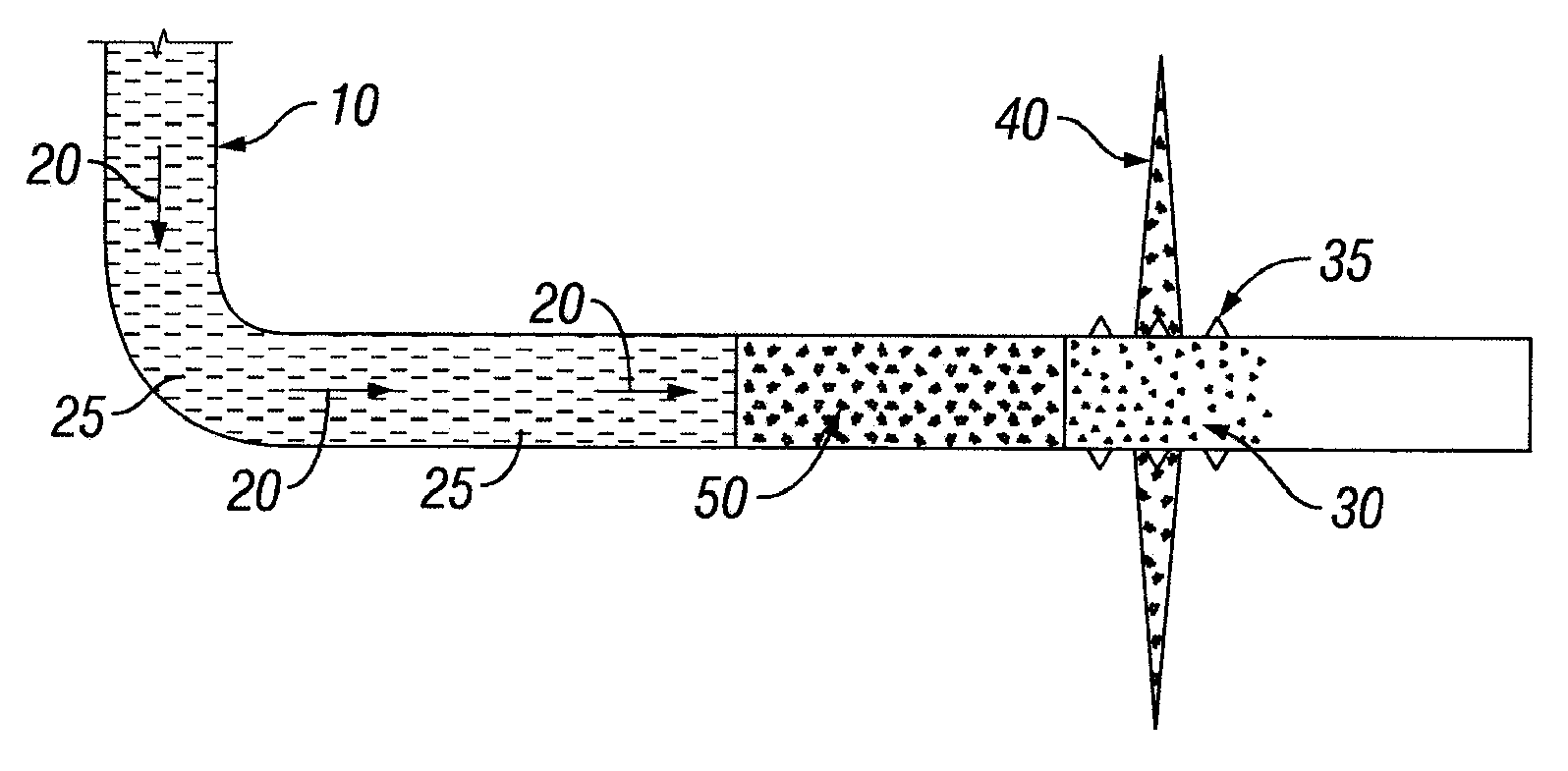
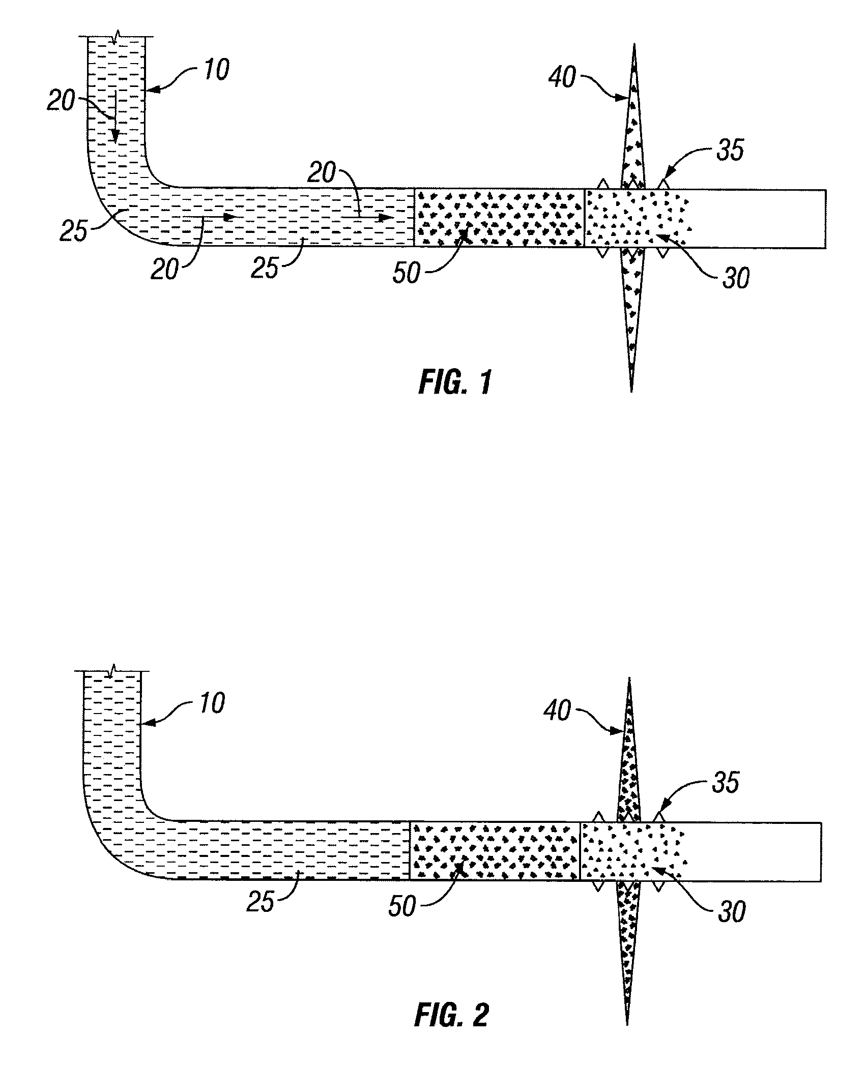
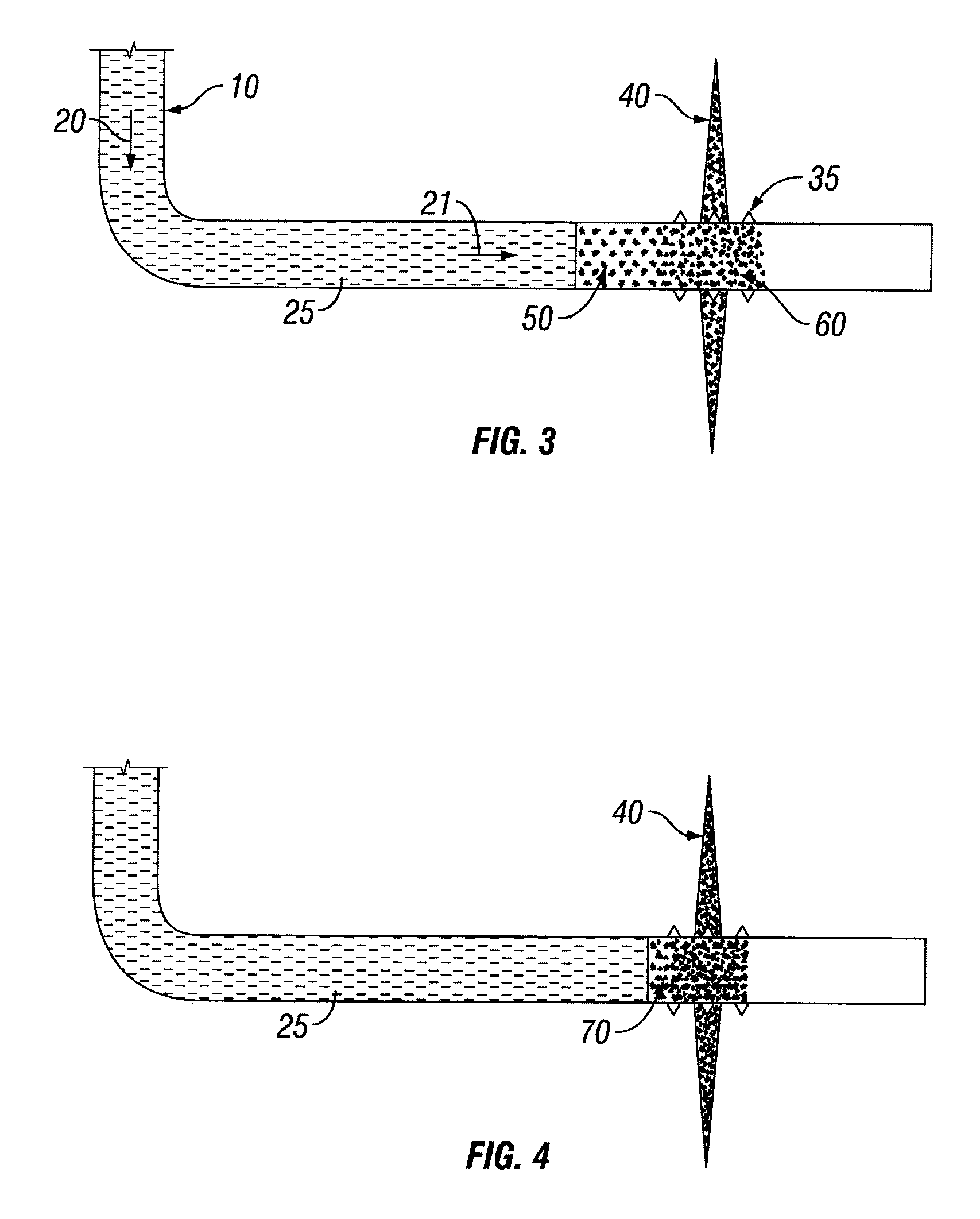
[0023]Illustrative embodiments and methods of the present invention are described below as they might be employed in the use of ultra lightweight or neutrally buoyant proppant to build a sand plug in a horizontal wellbore. In the interest of clarity, not all features of an actual implementation are described in this specification. It will of course be appreciated that in the development of any such actual embodiment or method, numerous implementation-specific decisions must be made to achieve the developers' specific goals, such as compliance with system-related and business-related constraints, which will vary from one implementation to another. Moreover, it will be appreciated that such a development effort might be complex and time-consuming, but would nevertheless be a routine undertaking for those of ordinary skill in the art having the benefit of this disclosure. Further aspects and advantages of the various embodiments of the invention will become apparent from consideration ...


PUM


Abstract

An improved method for building a plug in a horizontal wellbore using a fluid pill pumped into the wellbore at the end of a fracturing treatment. The fluid pill includes a high concentration of an ultra lightweight proppant, such as a neutrally buoyant proppant or an ultra lightweight proppant mixture. The fluid pill is pumped down the wellbore until it almost reaches fractures within a zone of interest. The pumping is then ceased or reduced, allowing the fractures to partially close. The ultra lightweight proppant remains suspended within the fluid pill while stationary. The pumping is then resumed at a very slow rate or as a short pump burst, thus causing the proppant in the fluid pill to bridge off until a bridge plug is formed.

Description

PRIORITY[0001]This application claims the benefit of U.S. Provisional Application No. 60 / 927,405 filed on May 2, 2007, entitled “METHOD OF ISOLATING OPEN PERFORMATIONS IN HORIZONTAL WELLBORES,” which is hereby incorporated by reference in its entirety.BACKGROUND OF THE INVENTION [0002]1. Field of the Invention[0003]The present invention, in general, relates to an improved method for building a proppant plug in a horizontal wellbore at a zone of interest and, more specifically, to utilizing a fluid pill containing a high concentration of ultra lightweight proppant in order to form a proppant plug in a horizontal wellbore.[0004]2. Description of the Related Art[0005]New hydrocarbon reserves are increasingly being discovered in lower quality reservoirs, particularly in North America. These lower quality reservoirs require some form of “stimulation” to increase the production of hydrocarbons from wells in these fields. Fracture stimulating a well to increase the production of hydrocarbo...

Claims


Application Information

Patent Timeline
Patent Type & Authority Applications(United States)
IPC IPC(8): E21B43/267
CPCE21B33/134E21B43/267E21B43/305
Inventor MISSELBROOK, JOHN GORDONMEYER, RUSSELLSCHULTZ, DARCY A.HAYES, TREVOR GORDONSTANG, QUENTIN SHANE
Owner BAKER HUGHES INC
Why Eureka
Try Eureka