Wind-driven electric power generation system

a technology of electric power generation and wind power, which is applied in the direction of wind energy generation, parallel air flow of wind motors, wind energy generation, etc., can solve the problems of wind power generation systems that face some difficulty in stability, and achieve the effects of reducing the amount of wind, facilitating the initial starting of the generator, and enhancing the effect of air pressur

Inactive Publication Date: 2008-11-06
MDL ENTERPRISES
View PDF8 Cites 31 Cited by
  • Summary
  • Abstract
  • Description
  • Claims
  • Application Information

AI Technical Summary

Benefits of technology

[0020]In accordance with another feature of the present invention, power conditioning can be provided to generated power if necessary using conditioning circuits known in the art (e.g., filtering circuits). The size of the present system is scalable to meet delivery requirements.
[0021]In accordance with another feature of the present invention, the housing can be made of a tough light weight metal or a composite that will be able to withstand harsh environments while meeting the highest of standards.
[0022]In accordance with another feature of the present invention, a cone can be located at the front of the generator / fan with its point facing facing incoming air / wind to cause the wind / air to flow directly onto fan blades and not encounter a flat surface typically associated with the back of a generator or center portion of a fan wherefrom blades extend. Pressure caused between the inner surface of the housing tubing and the cone / generator can force air directly onto the generator fan blades and outward past the fan blades where the air can be exhausted from the second end of the housing.
[0023]In accordance with another feature of the present invention, a cupped fan blade can be included to enhance the effect of air pressure on the fan blades and ultimately as rotation of the generator.
[0024]In accordance with another feature of the present invention, a clutching mechanism and / or mechanical breakaway can be provided to accommodate conditions where the wind speed exceeds rotational capabilities of the generator and / or power output requirements / thresholds. Clutching can be provided in the form of a fan blade assembly designed with materials that can flex above threshold rotational speeds (RPMs) in order to prevent operation of the generator above damage causing thresholds, design parameters and generator capacity limits.
[0025]In accordance with another feature of the present invention, an electronic starting circuit can be provided in order to facilitate initial starting of the generator from periods when the generator is idle (e.g., no rotation due to lack of wind). The electronic starting system can provide an initial release of electrical energy to the windings in the generator to thereby reduce the amount of wind required to spin-up or start rotation of the generator.

Problems solved by technology

The wind power generation system faces some difficulty in its stability due to fluctuation in direction and speed of air.

Method used


Image

  • Wind-driven electric power generation system
  • Wind-driven electric power generation system
  • Wind-driven electric power generation system

Examples


Embodiment Construction

[0041]The particular values and configurations discussed in these non-limiting examples can be varied and are cited merely to illustrate at least one embodiment and are not intended to limit the scope thereof.

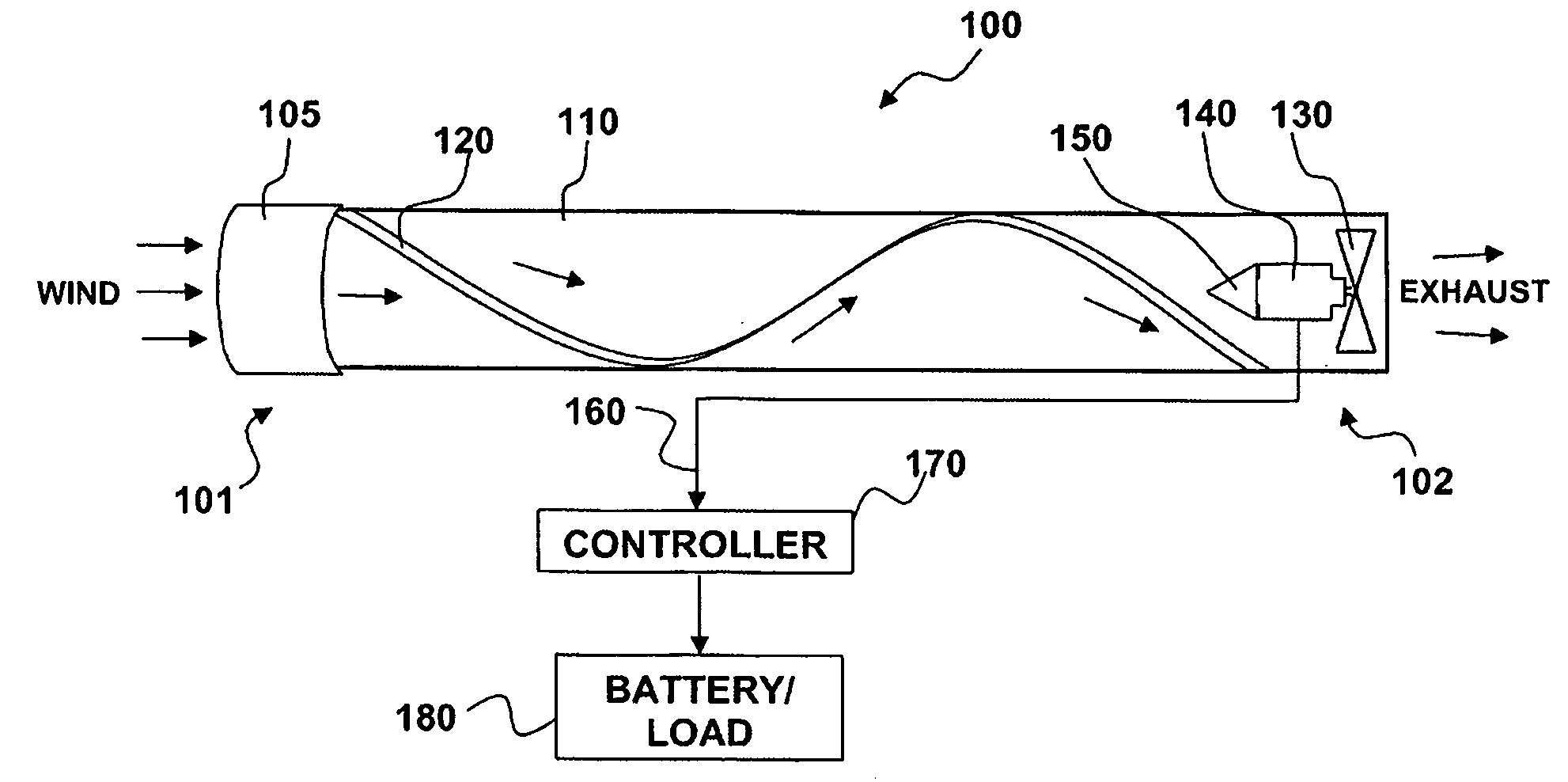
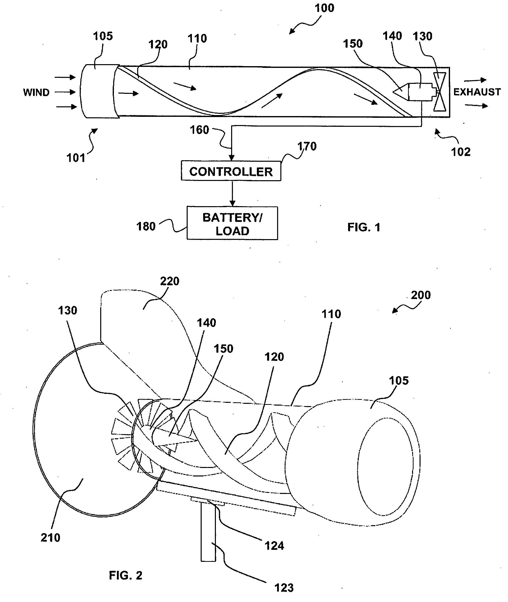
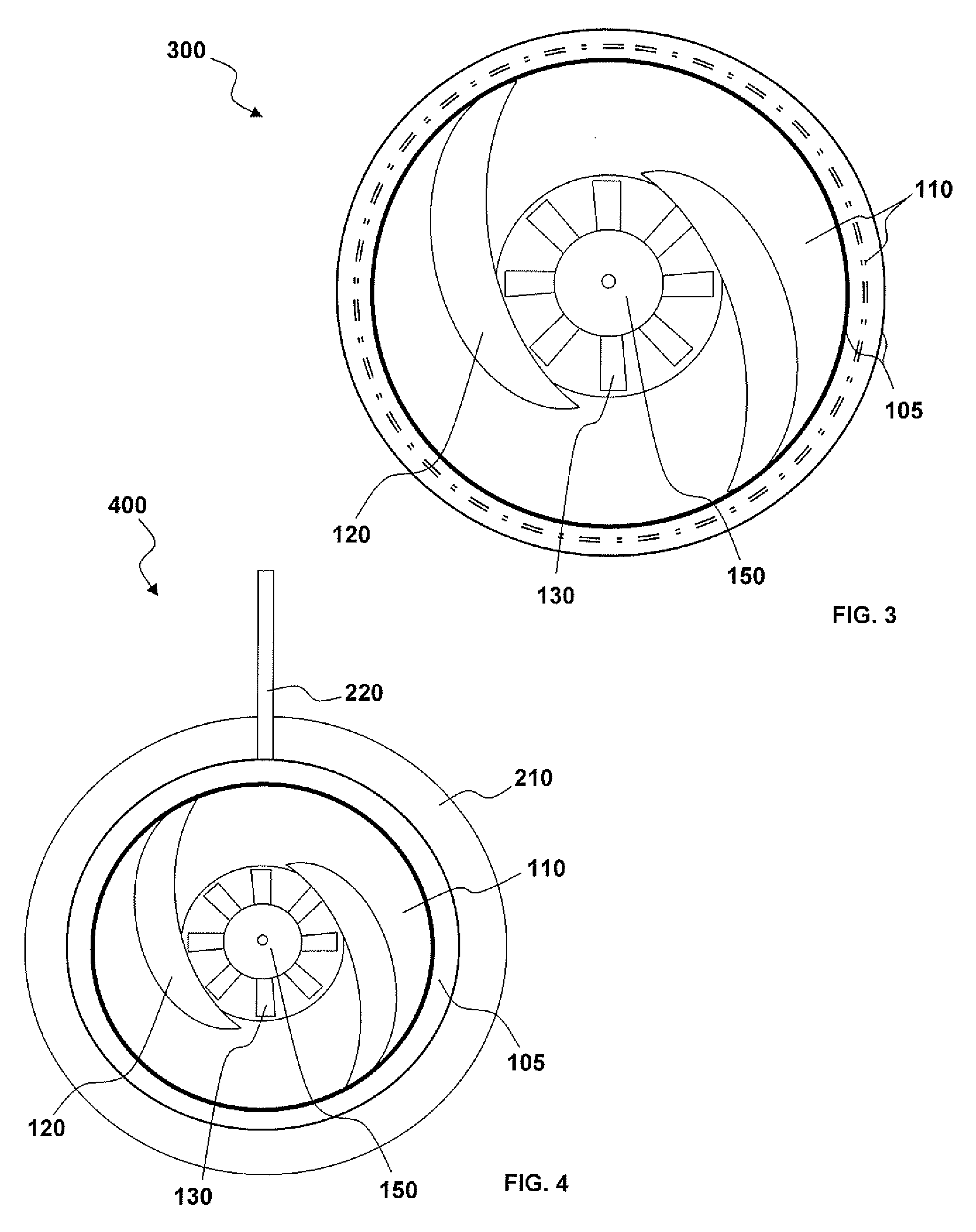
[0042]FIG. 1 illustrates a block diagram of a wind driven electrical power generating system 100, which can be implemented in accordance with a preferred embodiment. The system 100 has a cowling 105 to captured wind within a tubular housing 110 including at least one helical vane 120 formed therein which will rotate cause wind flowing as air through the tubular housing to spin as it approaches a fan 130 including fan blades mechanically connected to an electric generator 140 wherein electrical power can be generated as the fan 130 turns the electric generator 140. A generator cone 150 can be provided in front of the electrical generator 140, if the generator can be placed before the fan 130, or before the flat center portion of the fan (not shown), which supports fan blades ext...


PUM


Abstract

A system generating electrical power from wind includes a cowling to capture wind and directs it into a tubular housing. At least one fixed helical vane can be integrated into the inner surfaces of the tubular housing in a spiral, adapted to further direct the captured wind into a spiraled air flow and focus the wind directly onto electrical generator fan blades located near an exhaust of the system. A generator cone can be mounted at the front of the generator or fan blades facing air passing through the tubular housing. As air passes over the generator cone it can experience compression between the generator cone and housing resulting in increased pressure and velocity of the air, thereby increasing rotational speed of the generator blades and generator as the compressed air passes through the blades and exits the system's exhaust. The system can be used for fixed or mobile applications.

Description

TECHNICAL FIELD[0001]Priority is claimed to provisional patent application 60 / 921,331, filed Mar. 31, 2007, and also to provisional patent application 60 / 953,206, filed Jul. 31, 2007, both herein incorporated by reference.TECHNICAL FIELD[0002]The present invention is generally related to renewable energy systems. More particularly, the present invention is related to wind power generator systems adapted for fixed and mobile electrical power generation systems and applications.BACKGROUND OF THE INVENTION[0003]Wind is a force of nature that is all around us. It is harnessed to sail ships, pump water, and create electricity, just to name a few. Recent events in the world have highlighted the need for alternative methods of power production, whether it is from the wind, the sun, water, or organic matter. Changes in battery storage capacity and life and generator efficiency have made it so that individuals desiring to supplement their energy requirements may do so at a much more affordab...

Claims


Application Information

Patent Timeline
Patent Type & Authority Applications(United States)
IPC IPC(8): F03D9/00F03D1/04B60K16/00
CPCB60K6/485B60K16/00B60K2016/006B60W10/26B60W20/00B60W2510/244F03D1/04F03D9/002F05B2240/132F05B2240/941Y02T10/6226Y02T10/90Y02E10/725B60L53/52F03D9/25F03D9/32F03D9/34F03D13/20Y02E10/72Y02E10/728Y02T10/62Y02T10/70Y02T10/7072Y02T90/12B60L8/006
Inventor BACA, ANTHONY MICHAELWICHERS, DONALDORTIZ, LUIS M.
Owner MDL ENTERPRISES
Why Eureka
Try Eureka