System and apparatus for injecting droplets in a microfluidic system

a microfluidic system and droplet technology, applied in fluid controllers, laboratory glassware, instruments, etc., can solve the problems of high cost, high pressure control of the side reservoir of the pico-injector, and inability to properly operate the side reservoir

Pending Publication Date: 2022-05-26
WITHINGS SAS
View PDF0 Cites 0 Cited by
  • Summary
  • Abstract
  • Description
  • Claims
  • Application Information

AI Technical Summary

Problems solved by technology

However, such pico-injector requires very fine pressure control in the side reservoir to operate properly.
Such accurate absolute pressure control requires the use of expensive components.

Method used


Image

  • System and apparatus for injecting droplets in a microfluidic system
  • System and apparatus for injecting droplets in a microfluidic system
  • System and apparatus for injecting droplets in a microfluidic system

Examples


Embodiment Construction

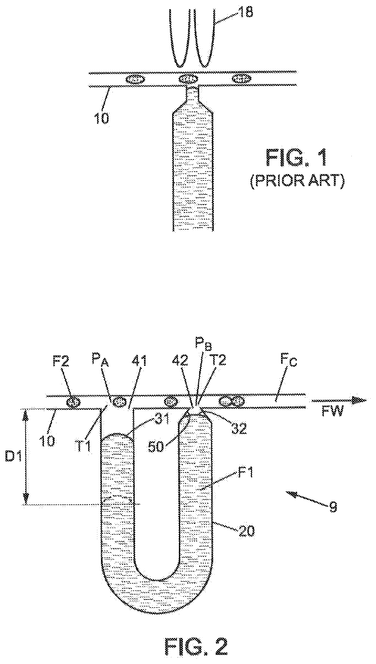
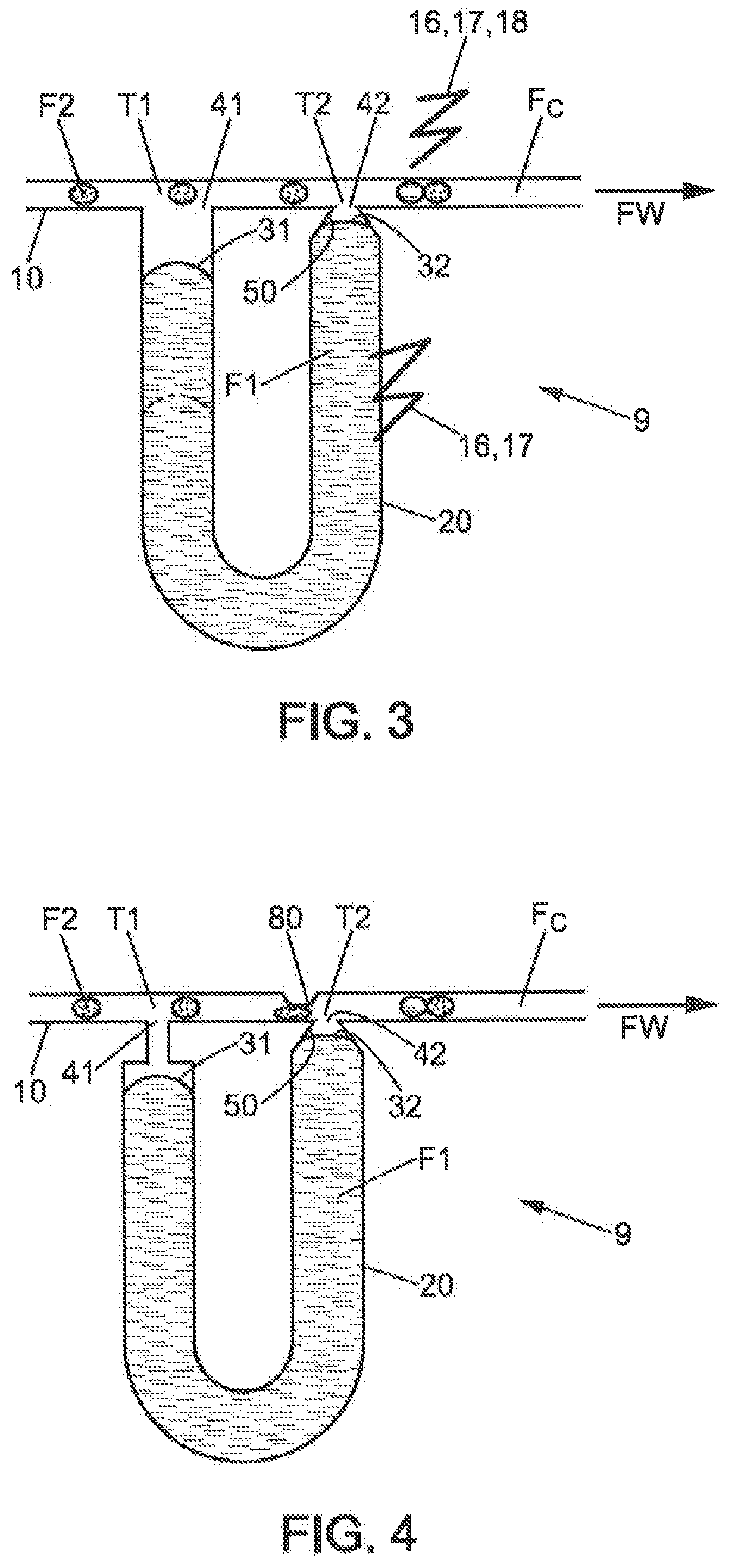
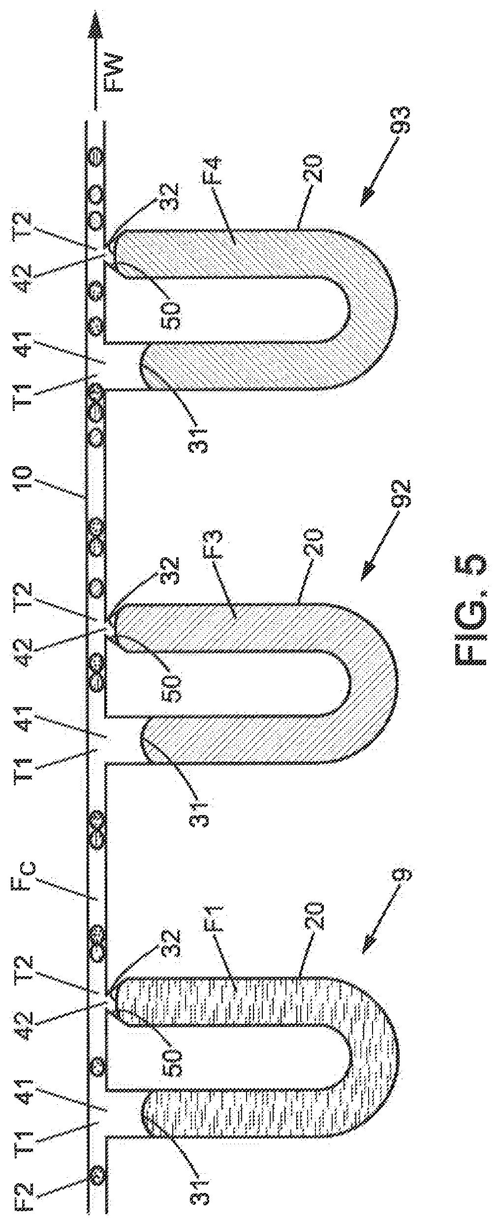
[0090]The present document promotes a device for delivering one or more release of a controlled volume of a first fluid with one or more droplets of a second fluid into a main channel with the use of a microfluidic device having micro-channels at a range from micrometer to millimeter. The micro-channels are treated in order to be hydrophobic. The micro-channels need to be hydrophobic when the carrier fluid is hydrophobic. However, the carrier fluid can also be hydrophilic and in such case, the micro-channels are hydrophilic. H This microfluidic device can work at ambient temperature or at another temperature.

[0091]As shown at FIG. 7, there is provided one or two pumps PC1, PC2 to circulate a carrier fluid denoted FC into a main channel denoted 10. Further, there is provided one pump P2 to release drop of a second fluid F2 into the main channel 10. The system composed of the pumps PC1 and P2 is classically a flow focusing geometry. This flow focusing is an example of generation of dr...


PUM

PropertyMeasurementUnit
aperture angleaaaaaaaaaa
volumeaaaaaaaaaa

Abstract

A microfluidic apparatus for delivering droplets of a first fluid to droplets of a second fluid, comprising a main channel, with a carrier fluid carrying droplets of the second fluid, an auxiliary channel, fluidly coupled to the main channel at a first intersection via a first orifice with a first fluid interface, and at a second intersection downstream to the first intersection via a second orifice with a second fluid interface, wherein a flow of the carrier fluid induces a difference of pressure between the first and second orifice generating a balance condition such that a meniscus of the second fluid interface is maintained in the auxiliary channel, at the vicinity of the second orifice, wherein a balance deviation triggers a release of a volume of the first fluid from the second fluid interface into the main channel.

Description

BACKGROUND AND PRIOR ART[0001]The present document relates to handling of fluids in microfluidic and milli-fluidic systems, and more particularly in so-called droplet systems, droplet microfluidics, which are used, for instance, in biochemical and biological analysis applications. The present document deals with mixing several fluids in a controlled manner.[0002]More specifically, the present application targets a two-phase flow in a micro-channel where droplets of a second fluid are transported by a carrier fluid. This micro-channel system allows the release of a controlled volume of a first fluid into a main channel when one droplet of the second fluid passes through an intersection between the main channel and an auxiliary channel.[0003]The principle of a pico-injector delivering of a droplet of a first fluid into a droplet of a second fluid, at a range from picoliter to microliter, has already been studied.[0004]Such pico-injector as illustrated in FIG. 1 is disclosed in documen...

Claims


Application Information

Patent Timeline
Patent Type & Authority Applications(United States)
IPC IPC(8): B01L3/00G01N35/08
CPCB01L3/502784G01N2035/1034G01N35/085B01L2200/0673B01L2300/088B01L2400/0688B01L3/0268B01L2200/027B01L2200/0605B01L2300/0663B01L2300/123B01L2300/14B01L2400/02B01L2400/0439
Inventor CARREEL, ERICLEGER, CHARLOTTECUNIASSE, PIERRE-ANTOINEMARTIN, ELIAN
Owner WITHINGS SAS
Why Eureka
Try Eureka