Eureka AIR delivers breakthrough ideas for toughest innovation challenges, trusted by R&D personnel around the world.

Airflow control devices based on active materials

a technology of active materials and airflow control, which is applied in the direction of air-flow influencers, roofs, transportation and packaging, etc., can solve the problems of downforce affecting vehicle stability and handling, devices generally do not adapt, and the airflow relative to the vehicle cannot be adjusted to better suit the changing driving conditions

Active Publication Date: 2008-11-06
GM GLOBAL TECH OPERATIONS LLC
View PDF47 Cites 62 Cited by
  • Summary
  • Abstract
  • Description
  • Claims
  • Application Information

AI Technical Summary

Benefits of technology

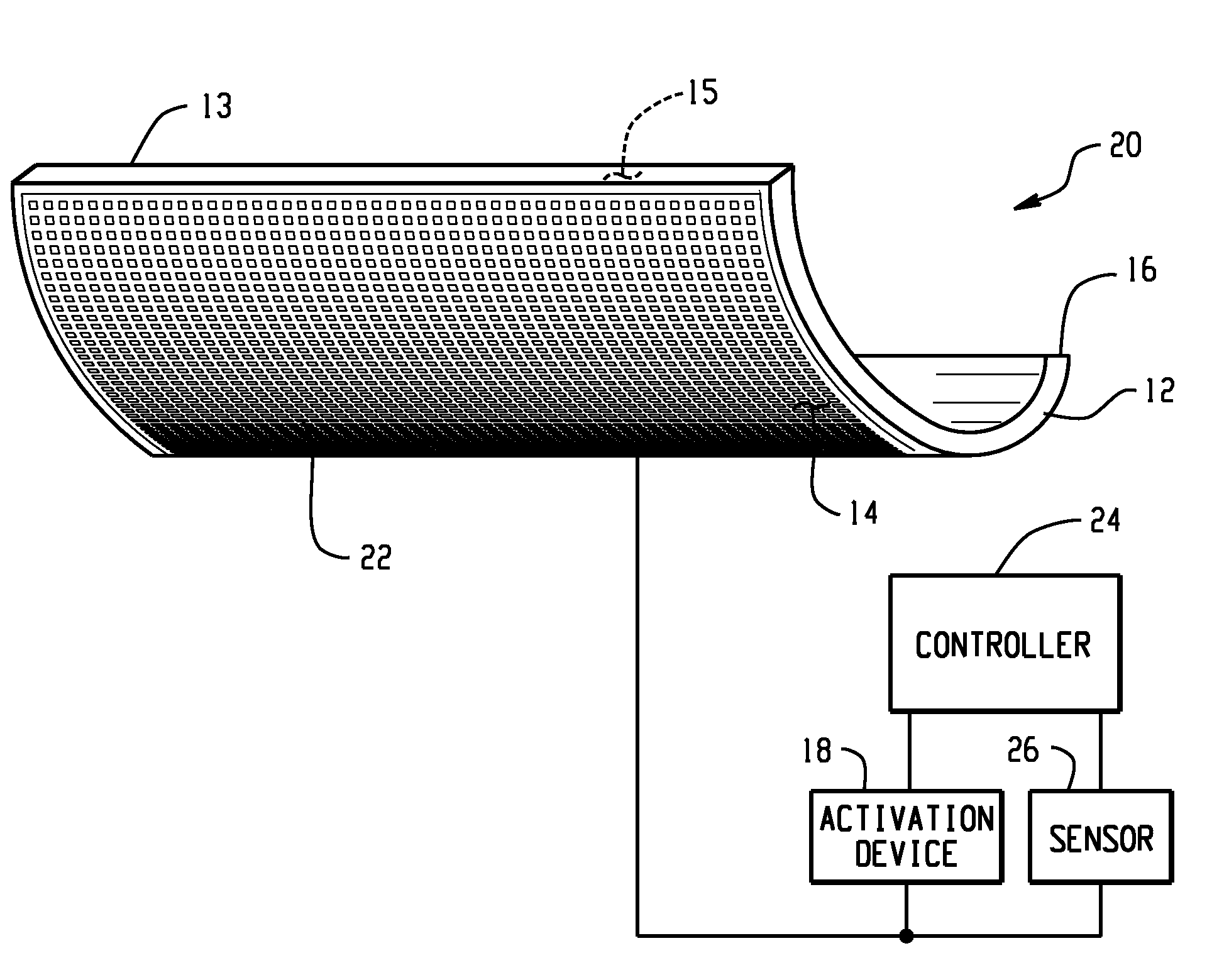
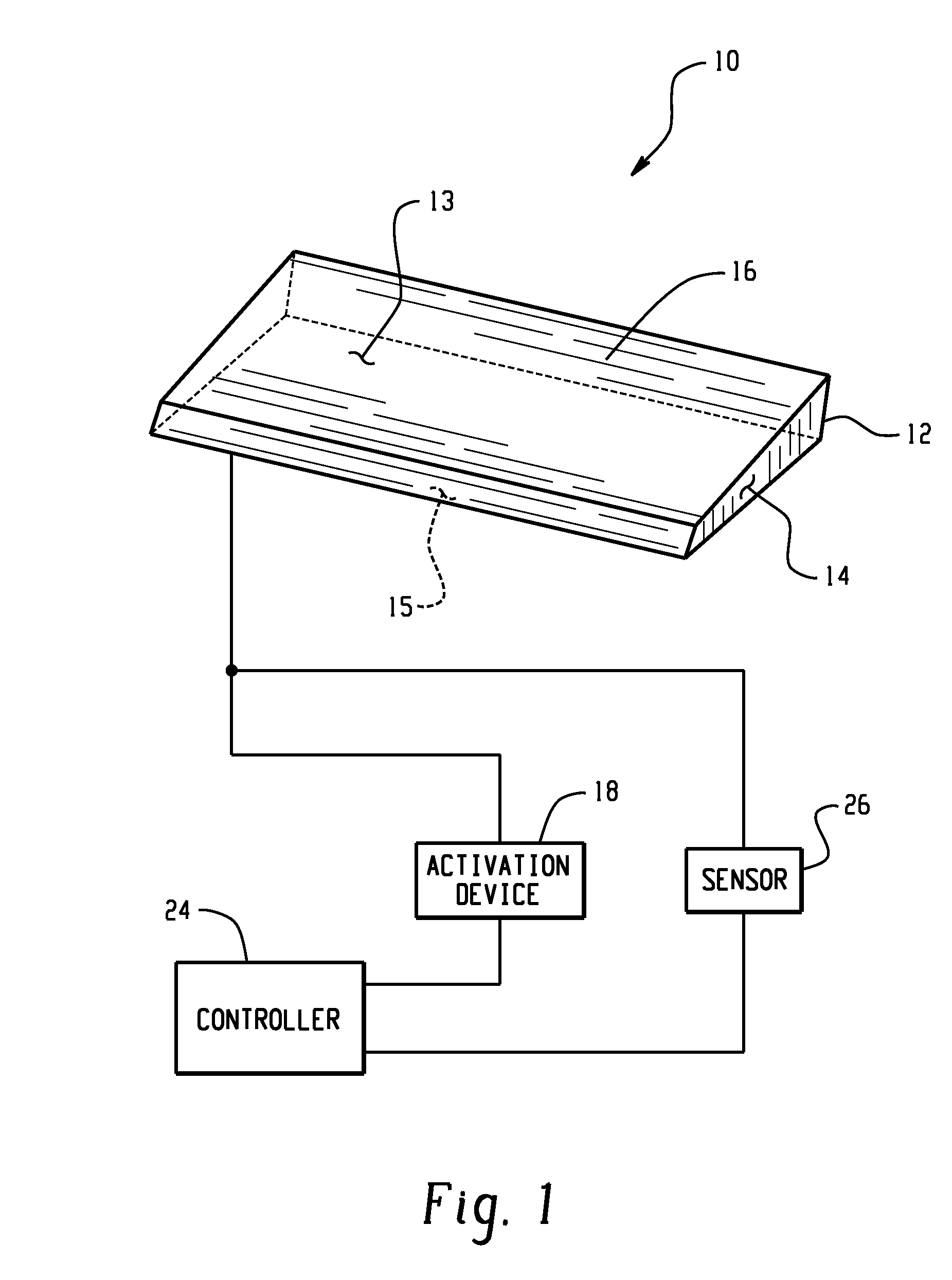
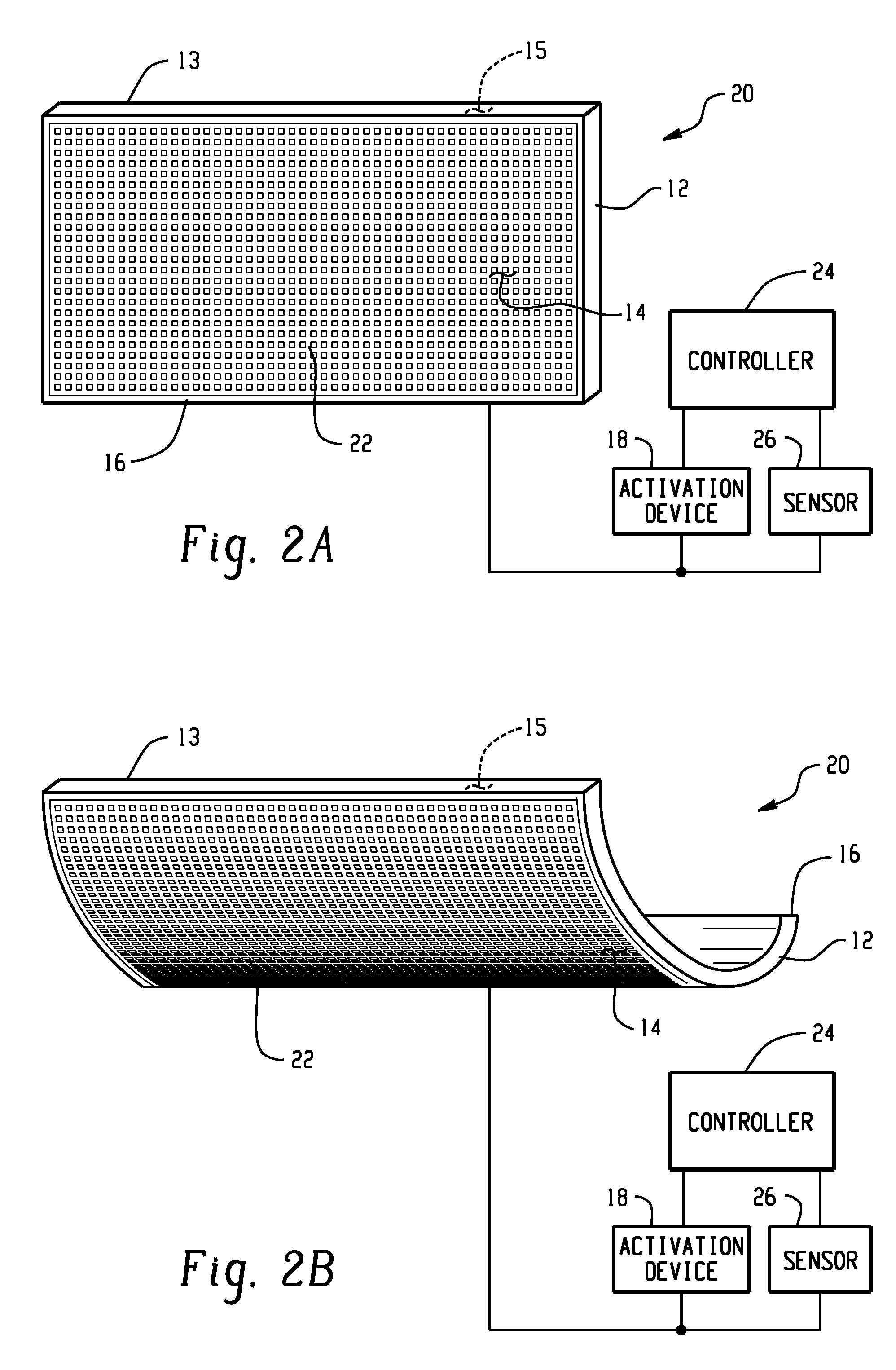
[0006]Disclosed herein is an airflow control device for a vehicle, i.e. air deflector. The air deflector comprises a body portion having at least one surface, and an active material in operative communication with the at least one surface, the active material being operative to change at least one attribute in response to an activation signal, wherein an airflow across the air deflector changes with the change in the at least one attribute of the active material.

Problems solved by technology

Vehicle lift and downforce can affect vehicle stability and handling.
Such devices generally do not adapt as driving conditions change, thus the airflow relative to the vehicle cannot be adjusted to better suit the changing driving conditions.
Vehicle designers are faced with the challenge of controlling the airflow while maintaining sufficient ground clearance to avoid contact with and damage by parking ramps, parking blocks, potholes, curbs and the like.
Further, inclement weather, such as deep snow slush or rainfall, can damage the device and / or impair vehicle handing.
However, such actuators generally require additional components such as pistons, motors, solenoids and / or like mechanisms for activation, which increase the complexity of the device often resulting in increased failure modes, maintenance, and manufacturing costs.

Method used


Image

  • Airflow control devices based on active materials
  • Airflow control devices based on active materials
  • Airflow control devices based on active materials

Examples


Embodiment Construction

[0024]The present disclosure provides an airflow control device for a vehicle, wherein the airflow control device is capable of reversibly changing shape, dimension, orientation, location and / or stiffness, the change being effected through the activation of an active material, allowing the airflow control device to adapt to varying driving conditions. Employing the active materials as described herein advantageously provides an actuation mechanism that is lightweight, inherently robust, and lower in complexity than prior external actuation means. Moreover, the airflow control devices described herein are also of low cost and of easily adaptable design that may be integrated with limited changes to the existing structure. As used herein the term “vehicles” includes any structure subject to airflow including, but not intended to be limited to, automobiles, over the highway tractors, boats, motorcycles, airplanes, bobsleds, spaceship, and the like.

[0025]As shown in FIG. 1, an airflow c...


PUM


Abstract

An airflow control device comprises a body and an active material in operative communication with the body. The active material, such as shape memory material, is operative to change at least one attribute in response to an activation signal. The active material can change its shape, dimensions and / or stiffness producing a change in at least one feature of the airflow control device such as shape, dimension, location, orientation, and / or stiffness to control vehicle airflow to better suit changes in driving conditions such as weather, ground clearance and speed, while reducing maintenance and the level of failure modes. As such, the device reduces vehicle damage due to inadequate ground clearance, while increasing vehicle stability and fuel economy. An activation device, controller and sensors may be employed to further control the change in at least one feature of the airflow control device such as shape, dimension, location, orientation, and / or stiffness of the device. A method for controlling vehicle airflow selectively introduces an activation signal to initiate a change of at least one feature of the device that can be reversed upon discontinuation of the activation signal.

Description

CROSS REFERENCE TO RELATED APPLICATIONS[0001]The present application is a divisional of, and claims priority to, U.S. patent application Ser. No. 11 / 086,469, filed on Nov. 5, 2004, incorporated herein in its entirety.BACKGROUND[0002]The present disclosure relates to devices for controlling vehicle airflow and, more particularly, to devices for controlling vehicle airflow which can be adjusted through changes in active materials in response to varying conditions, the adjustment being affected through shape, dimension, and / or stiffness changes in the active material.[0003]Airflow over, under, around, and / or through a vehicle can affect many aspects of vehicle performance including vehicle drag, vehicle lift and down force, and cooling / heat exchange for a vehicle powertrain and air conditioning systems. Reductions in vehicle drag improve fuel economy. Vehicle lift and downforce can affect vehicle stability and handling. As used herein, the term “airflow” refers to the motion of air aro...

Claims


Application Information

Patent Timeline
Patent Type & Authority Applications(United States)
IPC IPC(8): B62D37/02B64C1/00B64C3/00B64C5/00B64C23/00F15D1/10
CPCB64C2027/7288F15D1/10Y02T50/34B64C23/00Y02T50/30
Inventor MCKNIGHT, GEOFFREY P.MASSEY, CAMERONHERRERA, GUILLERMO A.BARVOSA-CARTER, WILLIAMJOHNSON, NANCY L.BROWNE, ALAN L.
Owner GM GLOBAL TECH OPERATIONS LLC
Why Eureka
Eureka Blog
Learn More