Ink Supplying Device, Recording Device, Ink Supplying Method and Recording Method

a technology of ink supply and printing head, which is applied in the direction of printing, other printing apparatus, etc., can solve the problems of degrading affecting the quality of printed images, and the negative pressure in the print head to rise, so as to stabilize the printing operation, minimize the negative pressure variations in the print head, and high quality

Inactive Publication Date: 2008-11-06
COPYER
View PDF12 Cites 82 Cited by
  • Summary
  • Abstract
  • Description
  • Claims
  • Application Information

AI Technical Summary

Benefits of technology

[0012]However, when an ink consumption per unit time by the print head increases sharply, there is a possibility that an ink supply may not be able to meet the demand, leaving the negative pressure in the print head to rise. If on the other hand the ink consumption per unit time falls sharply, the negative pressure in the print head may decrease by inertia of ink. Variations in the negative pressure in the print head will likely destabilize the ink ejection operation of the print head, degrading the quality of a printed image. Particularly, in an industrial printing apparatus that prints an image at high speed on a large-size print medium, an instantaneous ink consumption varies by a large margin, so the negative pressure in the print head easily changes. It is therefore important to minimize negative pressure variations in the print head in order to meet the demand for high print quality.
[0013]The object of this invention is to provide an ink supply device, a printing apparatus, an ink supply method and a printing method that can minimize negative pressure variations in the print head by positively controlling an ink supply pressure.
[0018]With this invention, the negative pressure variations in the print head can be minimized by positively controlling the negative pressure applied to the print head, which in turn can stabilize the printing operation using the print head and form an image of high quality.

Problems solved by technology

However, when an ink consumption per unit time by the print head increases sharply, there is a possibility that an ink supply may not be able to meet the demand, leaving the negative pressure in the print head to rise.
Variations in the negative pressure in the print head will likely destabilize the ink ejection operation of the print head, degrading the quality of a printed image.

Method used


Image

  • Ink Supplying Device, Recording Device, Ink Supplying Method and Recording Method
  • Ink Supplying Device, Recording Device, Ink Supplying Method and Recording Method
  • Ink Supplying Device, Recording Device, Ink Supplying Method and Recording Method

Examples


first embodiment

[0078]This embodiment represents a case in which a printing apparatus is incorporated in an image forming system such as shown in FIG. 1 and FIG. 2.

[0079](Overview of Image Forming System)

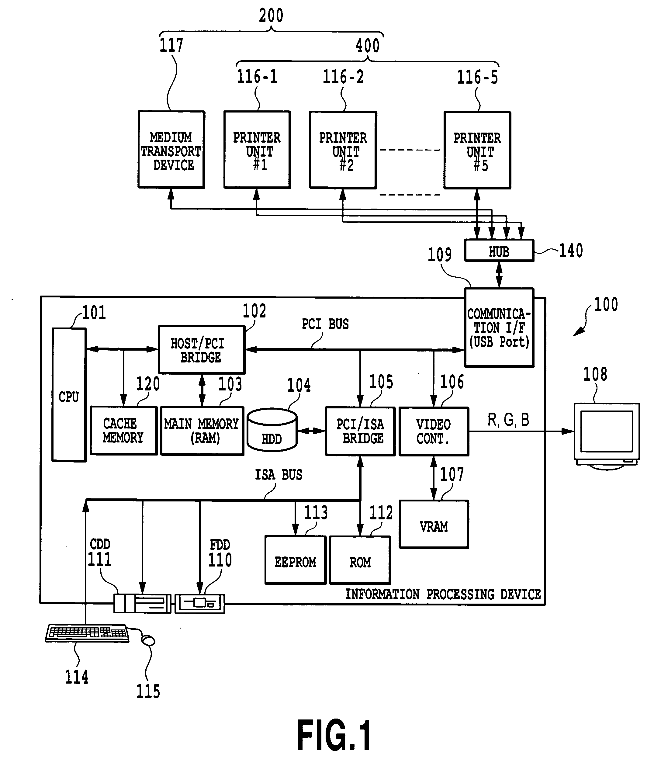
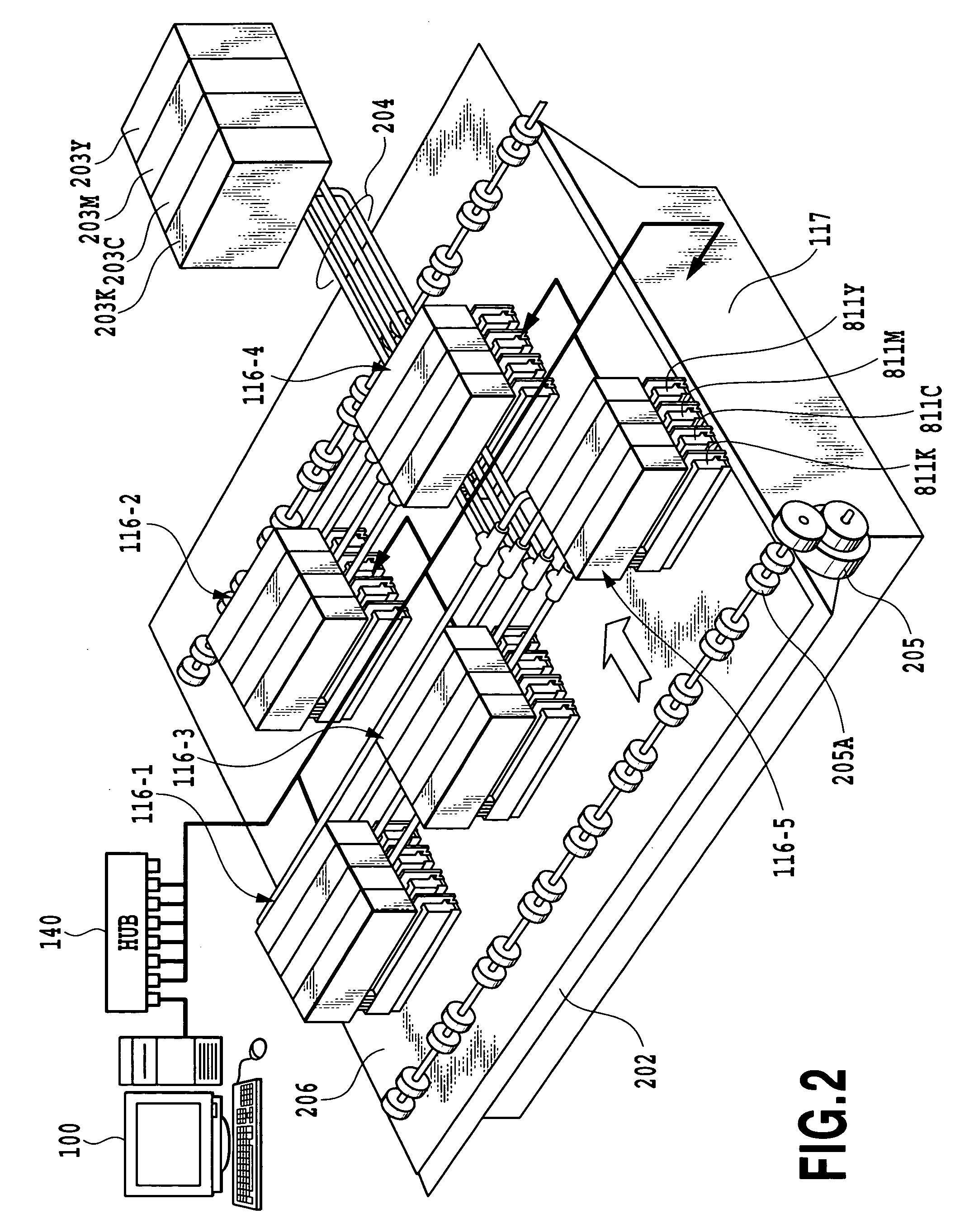
[0080]FIG. 1 and FIG. 2 are a block diagram and a schematic perspective view, respectively, showing an outline configuration of an image forming system. A printer composite system of this example comprises an information processing device 100 and an image forming device 200. The image forming device 200 has a medium transport device 117 and a printer composite system 400. The printer composite system has a plurality of independent engines or printer units (also referred to as “printing apparatus” or “printers”) 116-1 to 116-5.

[0081]The information processing device 100 is a source of data for an image to be formed, and divides one page of image into a plurality of areas and supplies a plurality of divided pieces of image data corresponding to the divided areas to a plurality of printer units 116-1 ...

second embodiment

[0207]FIG. 26 through FIG. 36 shows a second embodiment of this invention, and components identical with those of the preceding embodiment are given like reference numbers and their explanations are omitted.

[0208]This embodiment concerns an example case in which an apparatus of this invention is incorporated in the image forming system of FIG. 1 and FIG. 2. Thus, the outline of the image forming system in this embodiment is similar to that of the preceding embodiment.

[0209](Control System in Printer Unit)

[0210]FIG. 26 shows an example configuration of the control system in each printer unit 116. Components similar to those of the preceding embodiment are assigned like reference numbers and their explanations are omitted.

[0211]The pump motor 820 in this example is capable of forward and reverse rotation and drives a pump 548 (see FIG. 27) described later which is built into one end of the ink path of the print head 811 (811Y, 811M, 811C and 811K). The solenoid 821 in this example is ...

third embodiment

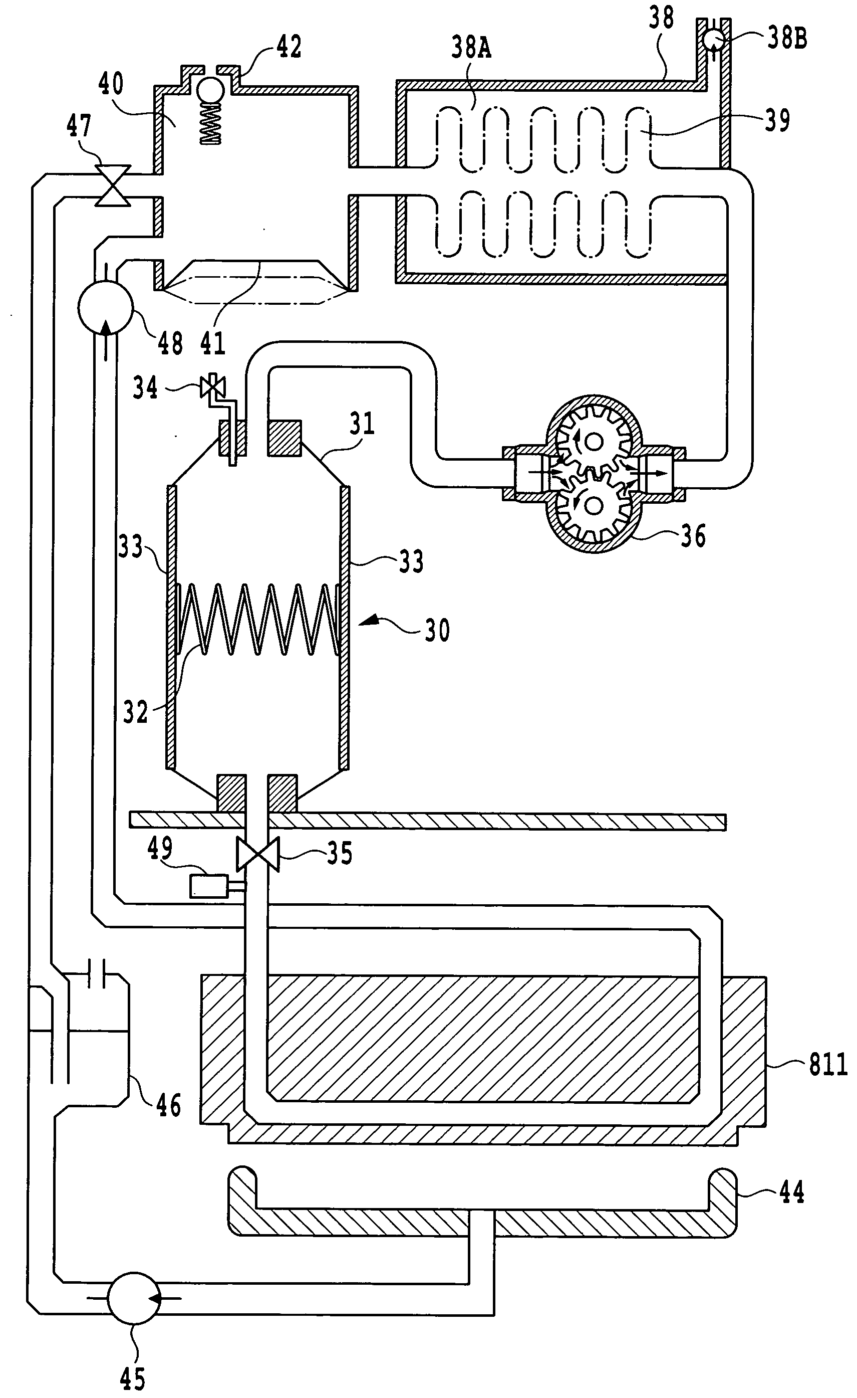
[0269]FIG. 37A and FIG. 37B show ink systems of different configurations.

[0270]The ink system of FIG. 37A, as in the first and second embodiment, has a negative pressure application means including a pump P and a valve V in an ink supply path L1 running between an ink tank T and a print head H. The pump P and the valve V correspond to the mechanical pump 36 and the pressure adjust valve 35 in the first embodiment and to the pressure adjust pump 536 and the pressure adjust valve 535 in the second embodiment. The print head H corresponds to the print head 811 in the first and the second embodiment. The ink communication path L1 is equivalent to the ink path for supplying ink from the ink tank to the print head 811 in the first embodiment and to the ink path for supplying ink from the ink tank 540 to the print head 811, i.e., the ink supply path 530 including the circulation path 531 and the connecting path 532, in the second embodiment.

[0271]As described above, FIG. 37A shows a constr...


PUM


Abstract

Variations in the negative pressure in the print head is minimized by positively controlling the ink supply pressure. For this purpose, the pump (36) and the valve (35) are installed in the ink communication path between the ink tank (40) and the print head (811), and are controlled to adjust the negative pressure applied to the print head (811).

Description

TECHNICAL FIELD[0001]The present invention relates to an ink supply device and an ink supply method to supply ink applied with a negative pressure to a print head, and a printing apparatus and a printing method to print an image by using the print head.BACKGROUND ART[0002]An ink jet printing apparatus that forms an image by ejecting ink from a print head onto a print medium can form a high-resolution image using a small print head having a plurality of nozzles arrayed at high density. The ink jet printing apparatus can also realize a color printing with a relatively inexpensive, compact construction that comprises a plurality of print heads and supplies a plurality of different color inks to the respective print heads. Therefore the ink jet printing apparatus is currently used in a variety of image output devices, such as printers, facsimiles and copying machines, whether for business use or for home use.[0003]In such an ink jet printing apparatus, it is important to maintain the in...

Claims


Application Information

Patent Timeline
Patent Type & Authority Applications(United States)
IPC IPC(8): B41J29/38B41J2/175
CPCB41J2/17556B41J2/17596
Inventor ISHINAGA, HIROYUKISONOBE, YOICHIHAIDA, KAZUOTAKAHASHI, YUICHI
Owner COPYER
Why Eureka
Try Eureka